Table of Contents

Summary of Contents for SEC Electronics PKN10
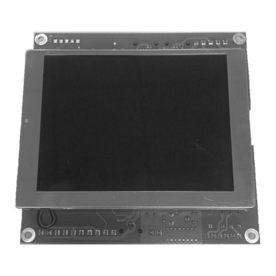
- Page 1 PKN10 serial node with colour LCD display User’s manual Bač 49a, 6253 Knežak, SLOVENIA tel: ++ 386 5 753 2006 fax: ++ 386 5 753 2007 email: sec.electronics@siol.net http://www.secelectro.com page 1 SEC Electronics PKN10 V0.3...
- Page 2 Connector for output direction indicators. Call button illumination. Customizable floor display tables. Serial communication compatible with all SEC controllers. Figure 1: PKN10, simplified front view with dimensions (all in mm) page 2 SEC Electronics PKN10 V0.3...
-
Page 3: Technical Specifications
Audio output: 5 W max. into 4 ohm Ambient temperature: max. 45°C Degree of protection: IP00 EMC: EN12015 in EN12016 Approvals: CE Figure 2: PKN10, rear view with connections page 3 SEC Electronics PKN10 V0.3... - Page 4 Terminal 1 is in Figure 2 on the left side. K8 pinout: pin 1: 0V pin 2: indicator up pin 3: indicator down pin 4: 0V Pin 1 is in Figure 2 on the left side. page 4 SEC Electronics PKN10 V0.3...
- Page 5 Figure 4 shows possible call pushbutton wiring in a group (an example on the figure is for duplex) when each lift has its own serial line with PKN10. Call and display operation is correct in all modes, including when one of lifts doesn’t work or is switched off.
-
Page 6: Power Supply
Power supply 24V DC is usually supplied to PKN10 via SSL serial link from the main controller module. However, the current that can be supplied via SSL link is limited to 1000 mA due to wiring and connector limitations. If jumpers J1 and J2 are removed, the module does not draw power from the SSL link and has to be connected to external power supply via K3. - Page 7 “proceed with firmware upgrade” otherwise you would have only “cancel firmware upgrade”. If the firmware update was successful, there will be a sign “Firmware upgrade OK, please turn PKN10 ON/OFF” and you would be returned to the upgrade setting. To make the firmware update make effect, switch off the device and turn it back on.
- Page 8 Other images : Name – not significant Format – BMP 320 x 240 16bit, RGB565 Wav files: PKN10 device checks wav files on the SD card at start- up, for the voice announcer. These files should have a specially assigned name and format.
-
Page 9: Configuration File
0 – Not active, travel direction is shown according to the controller settings. 1..48 – PKN10 shows direction only when car is in the preset station. display_starts_at the floor Default floor table is -2, -1, 0, 1, …, 48; display offset can be set with this parameter. - Page 10 PKN10 device in the same floor. 0 – Not active, setting for the first or the only PKN09 device in the same floor. 1 – Acts as a slave, setting for the second or the third PKN10 device in the same floor. pkn06_compatible 0 –...
- Page 11 A predefined eight-colour palette, is available in local configuration, is: 0 = black, 1 = blue, 2 = green, 3 = light blue, 4 = red, 5 = violet, 6 = yellow, 7 = white page 11 SEC Electronics PKN10 V0.3...
Need help?
Do you have a question about the PKN10 and is the answer not in the manual?
Questions and answers