Table of Contents
Advertisement
Quick Links
Advertisement
Table of Contents

Summary of Contents for ALPHA PLAM ALFA 90 PELET
- Page 1 USER MANUAL ALFA 90 PELET Ecological burning stove that heats your home ALFA PLAM...
- Page 2 Heating appliances (hereinafter referred to as "stove") of ALPHA PLAM are constructed and their technical acceptance test was performed on the basis of safety regulations stated in the referent European Union directives. This manual is intended for owners, installers, workers and staff responsible for stoves maintenance.
-
Page 3: Table Of Contents
TABLE OF CONTENTS INTRODUCTION PUTING INTO OPERATION AND USING OF THE STOVE SYMBOLS PELLET LOADING PURPOSE CONTROL PANEL DESCRIPTION PURPOSE AND CONTENTS OF THE START UP PHASE MANUAL STORING MANUAL 7.3.1 Electric Power UPDATING OFTHE MANUAL 7.3.2 Phase of work (ignition) GENERAL INFORMATION GENERAL PROVISIONS RELATING... -
Page 4: Introduction
REGULAR MAINTENANCE BY THE USERS DELIVERY AND TRANSPORT 8.2.1 Interior cleaning of furnace 8.2.2 Cleaning ashtray PREPARING SPACE FOR 8.2.3 Glass cleaning INSTALLATION PRECAUTION MEASURES 8.2.4 Chimney Cleaning GENERAL MEASURES 8.2.5 Setting of the lever PLACE FOR INSTALLING THE STOVE AIR USED FOR COMBUSTION INFORMATION ON THE DESTRUCTION AND TRANSPORT TO... -
Page 5: Purpose
PURPOSE The ALFA PLAM unit is a new stove for heating, with its advanced technology, which only uses pellets and and thanks to automatic operation creates a healthy and safe heat in space. The Stove shall work exclusively with a sealed combustion chamber door. Do not open the door when the stove is operating. -
Page 6: Manufacturer's
conduct checks as for the chimney and bringing of air, as for properly proposed installation solutions. In addition to that, all safety regulations and applicable special legislation of the state in which the stove is being installed have to be complied with. Except for the regulations listed in this manual, using the stove is to be in line with all applicable safety regulations provided for by special legislation of the state in which the stove is installed. -
Page 7: Spare Parts
maintenance of the stove, throughout its lifetime. Central office is at your disposal so as to refer you to your nearest qualified service facility. 1.12 SPARE PARTS Use only original spare parts. Do not wait for the parts to wear out from use before replacing them. Replacement of the seedily parts before the breaking leads to prevention of accidents that occur because of sudden breakage of parts, which can harm people and cause damage to property. -
Page 8: Warnings For Maintenance Workers
Make sure that the children do not approach the stove; - Adhere to the guidelines contained in this manual. Keep to the guidelines and warnings from the plates affixed to the stove On the plates, there are guidelines for preventing accidents at work, so they must always be fully readable. - Page 9 work on electrical, electronic parts and connectors. CHARACTERISTICS OF FUEL AND STOVE DESCRIPTION FUEL CHARACTERISTICS Pellets or wooden rollers (Figure 3.1) is a mixture of different kinds of wood compressed by mechanical procedures observing environment protection regulations It is the only kind of fuel prescribed for this kind of stove. Efficiency and thermal power of the stove can vary in accordance with the kind and quality of the used wooden rollers.
- Page 10 humidity. Moist or/and cold pellets (5 C) reduce the thermal power of fuel and require more detailed cleaning of the ember tray (of non-burned material) and combustion chamber. Special attention should be paid to storage and moving of the sacks with pellets. One should avoid its breaking and making of splinters.
-
Page 11: Delivery And Transport
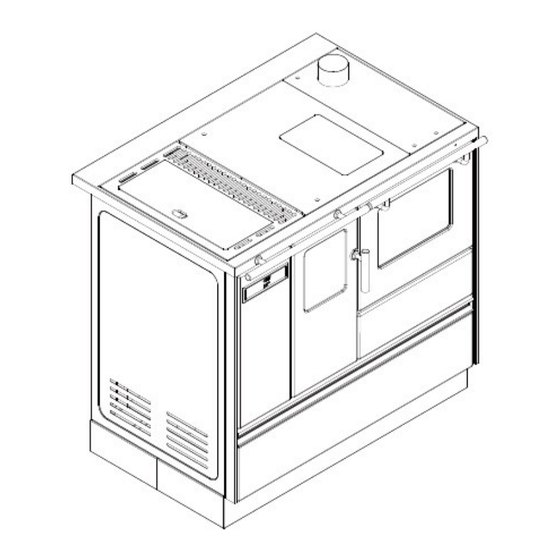
Fig.3.3.2 Fig. 3.3.3 DELIVERY AND TRANSPORT The stove is delivered with all the associated parts. Be careful – the stove has a tendency to turnover. Centre of gravity of the stove is moved to the left. Take care of the above stated even in case of the moving of the stove. During lifting avoid difficult moves. -
Page 12: General Measures
entrusted to carry out the checks in regard to the proposed installation The user is to comply with all the local, national and European safety regulations. Stove must be installed on the floor of the appropriate capacity. Instructions for assembly and disassembly of the stove are only intended for specialized technicians. -
Page 13: Air Used For Combustion
If the above stated conditions are not fulfilled, the stove cannot be installed. Fig.5.3.1 Fig.5.4.1 Fig.5.4.2 AIR USED FOR COMBUSTION stove, during its operation takes the air from the room in which it is located through the hole located on the rear right side of the stove. The place for taking air from outside can be linked with a hole in the wall by means of the pipe with a gasket, whose diameter is 80 mm. - Page 14 Air inlets should be placed at a height of 20-30 from the soil. From the outside, a grid must be placed for permanent ventilation, in very windy areas exposed to rain and wind, protection must be provided from rain and wind. If it is impossible to provide the room with outdoor air, it is possible to make an external opening in the adjoining room, but constant communication with the transit grid must be provided.
-
Page 15: Smoke Discharge
wool of minimal thickness of 2 cm) or steel pipes with double layer should be used, whereas, possibly, the vertical part, if internal, does not have to be double-layered. It is mandatory that the first vertical part should be at least 1,5 meter long so as to guarantee regular smoke discharge. -
Page 16: Installation
Fig.5.5.4 Fig.5.5.5 Wind damper Chimney Hermetic sealing Access eye In the case of a larger diameter chimney, it is necessary to "insert" in the same a steel pipe (with a diameter that corresponds to the chimney) and is isolated in an appropriate manner (Figure 5.5.1-2). Make sure the connection to the chimney in the wall is well sealed. - Page 17 Connecting to electricity (plug) must be easily accessible even after stove installment. If the supply cord is damaged, it must be replaced by technical assistance staff or by qualified technicians in order to avoid any risk. 6.1.1.1 Grounding It is mandatory to perform grounding and set up the differential switch in line with the applicable laws (Figure 6.1.1).
- Page 18 Fig.7.1.1 7.2 DESCRIPTION OF CONTROL PANEL FIG.7.2 The control panel consists of two LCD displays with backlight, ON / OFF (D) keys, the key to set the operation MENU (C) , four menu buttons A, B, E, F and 6 LEDs that display the state of functioning the stove.
- Page 19 LED – activated timer LED – coil operation LED – deactivation LED – room thermostat To access the menu: Press the menu key (C). Press the menu key (C) several times to browse different menus. The display G will show Set/parametro (Settings/parameter). The display H will show temperature or parameter value.
- Page 20 Fig.7.3.5 The coil for loading pellets is powered. Starting the coil is marked by turning LED ( M ). Fig.7.3.6 The display will show captions “Load” (loading) and “Wood” (wood). Automatic ignition: the stove is equipped with an automatic device that allows the burning of pellets without the use of other traditional means of ignition.
- Page 21 Defines the desired room temperature. For example: the display will show the captions “SET” (settings) and “20 C”. FIG.7.4.3 Press the keys ( A ) and ( B ) to increase or decrease the temperature. After three seconds, the values will be automatically saved. AIR SPEED (the value between A, 1-5) Defines the speed of the air exchanger.
- Page 22 The power P5 should only be used for heating or cooking food on the rack set on the upper level. SWITCHING OFF FIG.7.5.1 To switch off the stove, hold the key On/Off (D) for a few seconds. Example: the display will show the captions “OFF” and “19.27”. The coil for loading pallets will stop immediately while the fan will be automatically switched off when the stove cools down.
- Page 23 FIG.7.6.2 FIG.7.6.3 Select the hour by pressing the keys (A) and (B). To confirm the selection, press the key menu (C). Press the key “UT03” MINUTO CORRENTE (current minute) – the values between 00 and 60. Select the minute by pressing the keys (A) i (B). To confirm the selection, press the key menu(C).
- Page 24 Thursday 6.30 - 22.00 Friday 6.30 - 22.00 Saturday 8.00 - 20.00 Sunday 8.00 - 20.00 You have to set the parameters as follows: UT05 6.30, UT06 20.30, UT07 (on1, off2, on3, off4, off5, off6, off7) UT08 5.00, UT09 22.00, UT10 (off1, on2, off3, off4, off5, off6, off7) UT11 6.30, UT12 22.00, UT13 (off1, off2, off3, on4, on5, off6, off7) UT14 8.00, UT15 20.00, UT16 (off1, off2, off3, off4, off5, on6, on7) ALARMS...
- Page 25 It appears in the case of a failure or turning off the probe for smoke detection. For the duration of the alarm, the stove performs the extinction operation. 7.7.4 Alarm ALar dEP (alarm for depression) FIG.7.7.4 It appears when there are irregularities related to: chimney draft, i.e.
-
Page 26: Regular Maintenance By The Users
A message “ALarSic” (safety alarm) is displayed and the system stops. CLEANING EMBER TRAY FIG.7.8.1 It may be that during normal stove operation, at certain intervals, the message “Pulizia Braciera” (CLEANING EMBER TRAY) is activated. The message “StoP FirE” is displayed. MAINTENANCE AND CLEANING SAFETY MEASURES Before undertaking any maintenance operation, apply the following safety measures... - Page 27 FIG.8.2.1-2 Clean the smoke extractor by removing panels from the baking plate (Figure 8.2.1-3). FIG.8.2.1-3 Clean the area for extracting smoke (Figure 8.2.1-4). FIG.8.2.1-4 Clean the area where the precipitation remains below the oven (Figure 8.2.1-5).
-
Page 28: Cleaning Ashtray
FIG.8.2.1-5 The presence of condensation is an indicator of possible infiltration of water or over- cooling of smoke. It is advisable to determine the possible reasons in order to enable the stove to work properly again. 8.2.2 Cleaning ashtray Cleaning the ashtray is done once a week or as needed. To reach the ashtray, open the door in front of the ashtray. -
Page 29: Information On The Destruction And Transport To Landfill
bad combustion; glass browning; clogging of the ember tray due to deposition of ashes and pellets; deposition of ashes and excessive deposition on the exchanger, which leads to poor performance of the stove. Valve against the wind (Figure 8.2.4-1) Access eye (Figure 8.2.4-1) FIG.8.2.4-1 INFORMATION ON THE DESTRUCTION AND TRANSPORT TO LANDFILL Destruction of the stove and its transport to landfill is the exclusive responsibility of the... -
Page 30: Control Panel
10 ELECTRICAL SCHEMES 220 - 240 V 50 Hz UZEMLJENJE PRIKLJUČNI OSIGURAČ 2A KABAL PREKIDAČ BRAON BRAON DIMNI BRAON GASOVI CRVENA TOPAO CONDENZATOR CRVENA VAZDUH CONDENZATOR CRNA PLAVA PUŽ BELA UPALJAČ BELA RELEJ PLAVA CRVENA VENTILATOR TOPLOG VENTILATOR VAZDUHA IZDUVNIH GASOVA CN13 TERMOSTAT... -
Page 31: Technical Specifications
HOME PLATE LEGEND SYMBOL Fuel Pmax Nominal thermal power to room Pmin Reduced thermal power to room Pwmax Nominal power to water Pwmin Reduced power to water Maximum operating pressure EFFmax Nominal effect EFFmin Effect with reduced power COmax(13% O CO emissions at nominal power (13% O COmin(13% O CO emissions at reduced power (13% O... - Page 32 Stove intended for the area not smaller than 40 m REQUIREMENTS ON ELECTRICAL POWER Voltage 230 V Frequency 50 Hz Maximum absorbed power during operation 110 W Absorbed power on ignition 400 W DIMENSIONS Minimal dimension that is variable depending on setting the pins Dimensions (cm)
- Page 33 TIME OF GUARANTEED SERVICING This implies the period during which we guarantee the service, accessories and space parts, starting from the day of purchase of the device. The time of guaranteed servicing is in accordance with the valid legal regulations. In case of change of the model and the design of the device, the term for change of parts that have modified design is within the legal term.
Need help?
Do you have a question about the ALFA 90 PELET and is the answer not in the manual?
Questions and answers