
Related Manuals for VIA Technologies NSD7800

Summary of Contents for VIA Technologies NSD7800
- Page 1 NSD7800 NSD7800 NSD7800 NSD7800 U U U U ’ ’ ’ ’ M M M M S S S S ANUAL ANUAL ANUAL ANUAL Version 1.00 November 24, 2008...
- Page 2 Disclaimer Disclaimer No license is granted, implied or otherwise, under any patent or patent rights of VIA Technologies. VIA Technologies makes no warranties, implied or otherwise, in regard to this document and to the products described in this document. The information provided in this document is believed to be accurate and reliable as of the publication date of this document.
- Page 3 S S S S I I I I AFETY AFETY NSTRUCTIONS NSTRUCTIONS AFETY AFETY NSTRUCTIONS NSTRUCTIONS Lay this equipment on a reliable flat surface before setting it up. Always unplug the power cord before inserting any add-on card or module. Make sure the voltage of the power source and adjust properly 110/220V before connecting the equipment to the power inlet.
- Page 4 P P P P C C C C L L L L ACKAGE ACKAGE HECK HECK ACKAGE ACKAGE HECK HECK NSD7800 system unit x 1 HDD screws (M3*4L) x 32 “Powered by VIA” label...
-
Page 5: Table Of Contents
ABLE OF ABLE OF ONTENTS ONTENTS ABLE OF ABLE OF ONTENTS ONTENTS NSD7800 Overview NSD7800 Overview......................1 NSD7800 Overview NSD7800 Overview Specifications .........................1 Layout ..........................3 System indicators......................5 Hard disk activity indicator .................5 Hard disk status indicator ...................5 System power indicator ..................5 System hard disk activity indicator..............5... -
Page 6: Nsd7800 Overview
NSD7800 User’s Manual NSD7800 NSD7800 O O O O NSD7800 NSD7800 VERVIEW VERVIEW VERVIEW VERVIEW Specifications Specifications Specifications Specifications Processor Processor Processor Processor ® • VIA C7 -D 1.5 GHz NanoBGA2 processor Chipset Chipset Chipset Chipset • VIA CN700 North Bridge •... - Page 7 NSD7800 User’s Manual Power Power Supply Supply Power Power Supply Supply • 300W ATX power supply System Monitoring and Management System Monitoring and Management System Monitoring and Management System Monitoring and Management • Wake-on LAN • Watch Dog Timer •...
-
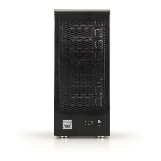
Page 8: Layout
NSD7800 User’s Manual Layout Layout Layout Layout 3 3 3 3... - Page 9 NSD7800 User’s Manual 4 4 4 4...
-
Page 10: System Indicators
System indicators System indicators System indicators System indicators The NSD7800 is equipped with several indicators. The description of these indicators is as follows. Hard disk activity indicator Each hard disk tray has an independent hard disk activity indicator. This indicator lights up whenever the hard disk is in use. -
Page 11: System Components
NSD7800 User’s Manual System System components components System System components components Hard disk tray There are a total of eight hard disk trays in the system. Each tray can support one 3.5 inch SATA hard disk. SATA (300 Mbps) or SATA (150 Mbps) may be used in the system. -
Page 12: Installing The Components
NSD7800 User’s Manual I I I I C C C C N N N N STALLING STALLING STALLING STALLING THE OMPONENTS OMPONENTS OMPONENTS OMPONENTS Opening the Chassis Opening the Chassis Opening the Chassis Opening the Chassis Step 1 Step 1... - Page 13 NSD7800 User’s Manual Step Step 2 2 2 2 Step Step Slide out the chassis side panel to access the internal components. 8 8 8 8...
- Page 14 NSD7800 User’s Manual Step Step 3 3 3 3 Step Step The mainboard is located as shown in the figure below. Note: Note: Note: Note: For mainboard specific information, please refer to the VIA NAS7800 user manual. 9 9 9 9...
-
Page 15: Installing The Hard Drives
NSD7800 User’s Manual Installing the hard drives Installing the hard drives Installing the hard drives Installing the hard drives Step 1 Step 1 Step 1 Step 1 Slide the hard drive into the tray. Step 2 Step 2 Step 2... - Page 16 NSD7800 User’s Manual Step 3 Step 3 Step 3 Step 3 Ensure that the tray lock is not engaged. Pull the latch (shown in green) to the right to release the lock. Note: Note: Note: Note: If the lock is not released prior to inserting the hard drive tray, the hard drive cannot be properly inserted and the tray will be jammed in the hard drive bay.
- Page 17 NSD7800 User’s Manual Step Step 4 4 4 4 Step Step With the tray lock disengaged, load the hard drive tray into the hard drive bay.
- Page 18 NSD7800 User’s Manual Step Step 5 5 5 5 Step Step After the hard drive tray has been fully inserted into the hard drive bay, engage the hard drive lock.
-
Page 19: Applying The Label
NSD7800 User’s Manual Applying Applying the label the label Applying Applying the label the label To apply the VIA label, remove the protective non-adhesive backing from the label. Then apply the label to the chassis. The included VIA label is 25.6 mm (width) by 25.6 mm (height) by 0.5... -
Page 20: System Rec System Recovery System Rec Overy
System Recovery Overview System Recovery Overview The NSD7800 comes with a recovery button on the exterior of the chassis. When the recovery button on the NSD7800 is pressed, the system will be reset and all other boot priorities will be overridden at that time. -
Page 21: Setting Up The Bios For System Recovery
The BIOS settings can be changed using the following simple procedure. Step 1 Step 1 Step 1 Step 1 Boot up the NSD7800. As soon as “Press DEL to enter SETUP” appears, press <DEL> <DEL>. <DEL> <DEL> S S S S tep 2... - Page 22 NSD7800 User’s Manual Step 3 Step 3 Step 3 Step 3 In the “Advanced BIOS Features” menu, select “Recovery Boot Support” and press <ENTER> <ENTER>. A dialog window will be displayed with the <ENTER> <ENTER> following options: • Disabled •...
- Page 23 Step Press <ESC> <ESC> to exit to the main menu. <ESC> <ESC> Step Step Step Step 6 6 6 6 Select “Save & Exit Setup” and press <ENTER> <ENTER>. <ENTER> <ENTER> The changes will take effect after the NSD7800 reboots.
-
Page 24: Initiating The System Recovery Process
NSD7800 User’s Manual Initiating the System Recovery Process Initiating the System Recovery Process Initiating the System Recovery Process Initiating the System Recovery Process Once the BIOS has the appropriate settings, initiating the system recovery process is as easy as pushing a button — literally. -
Page 25: Setting The Status Indicators
NSD7800 User’s Manual S S S S S S S S I I I I ETTING THE ETTING THE ETTING THE ETTING THE TATUS TATUS TATUS TATUS NDICATORS NDICATORS NDICATORS NDICATORS The hard drive status indicators must be programmed in order for them to function. - Page 26 NSD7800 User’s Manual HDD Tray Color Remarks Tray 4 Green GPO6=0, GPO7=1 GPO6 for Green LED GPO7 for Red LED GPO6=1, GPO7=0 Orange GPO6=0, GPO7=0 GPO0=6, GPO7=1 Tray 5 Green GPO8=0, GPO9=1 GPO8 for Green LED GPO9 for Red LED...
-
Page 27: Gpio Control
NSD7800 User’s Manual GPIO control GPIO control GPIO control GPIO control The following table shows the GPIO control porting for the W83697HG. Signal Signal Select Register Data Port GPO0 Chip Global CR2A[6] = 0 LD9_CRF4[0] LD9_CR30[1] = 1 (Read / Write) - Page 28 NSD7800 User’s Manual Signal Signal Select Register Data Port GPO9 Chip Global CR2A[5] = 0 LD9_CRF7[1] LD9_CR30[2] = 1 (Read / Write) LD9_CRF6[1] =0 LD9_CRF8[1] = 0 GPO10 Chip Global CR2A[7] = 0 LD9_CRF1[0] LD9_CR30[0] = 1 (Read / Write)
-
Page 29: Related Register Description
NSD7800 User’s Manual Related Register Description Related Register Description Related Register Description Related Register Description The following register descriptions have been excerpted from Winbond LPC I/O W83697HF data sheet revision 2.0. - Page 30 NSD7800 User’s Manual The following is sample code from the same data sheet.
Need help?
Do you have a question about the NSD7800 and is the answer not in the manual?
Questions and answers