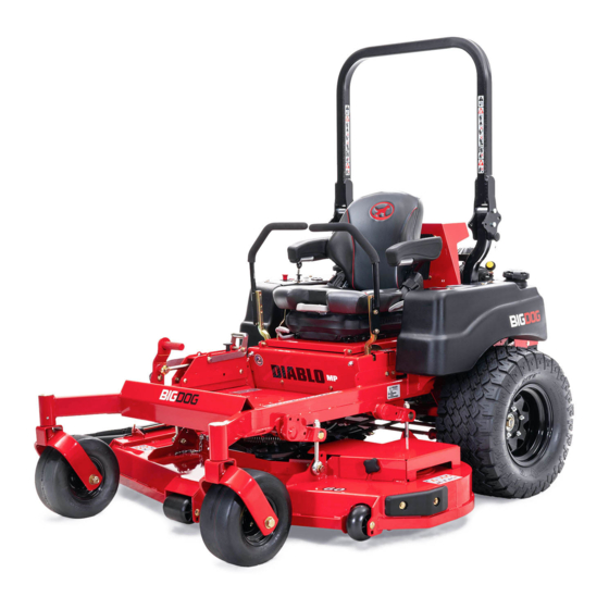
BigDog Diablo MP Service Manual
Hide thumbs
Also See for Diablo MP:
- Operator's manual (45 pages) ,
- Operator's manual (49 pages) ,
- General service manual (45 pages)

Related Manuals for BigDog Diablo MP


Summary of Contents for BigDog Diablo MP
- Page 1 BigDog ® Mowers Diablo ® General Service Manual 200 South Ridge Road Hesston, Kansas 67062 120125 REV B...
- Page 2 WARNING WARNING The engine exhaust from this product contains chemicals known to the state of California to cause cancer, birth defects or other reproductive harm. NOTICE OF REQUIREMENT OF SPARK ARRESTER MUFFLER This equipment may create sparks that can start fires around dry vegetation. California Public Resources Code Section 4442.6 provides that it is unlawful to use or operate an internal combustion engine on any forest-covered, brush-covered, or grass-covered land unless the engine is equipped with a spark arrester maintained in effective working order.
-
Page 3: Table Of Contents
General Information ........1-1 BigDog Mower Service Program. - Page 4 Electrical ..........7-1 Electrical Schematic –...
-
Page 5: General Information
BigDog Mower Service Program hydraulic assemblies. Daily inspect mower for grass clippings and wire and string This manual is part of a service package for the BigDog ® Diablo ® MP mowers. Use of this manual in conjunction with tangles. - Page 6 REV B 120125...
-
Page 7: Safety
SAFETY explosive. A fire or explosion from fuel can burn you and others and can damage property. • Refuel outdoors. Never refuel or drain the fuel from the machine indoors. • Never attempt to start engine when there is a strong This safety alert symbol is used to call attention to a message odor of gasoline or diesel fuel fumes present. -
Page 8: Operation Precautions
Keep all safety shields and covers in place, except for wear gloves and use extra caution when servicing them. servicing. ® Use only genuine BigDog Mower replacement parts to Do not touch hot parts of machine. ensure that original standards are maintained. - Page 9 tape openings after adding the inhibitor. Keep container parts water and one part baking soda when they tightly closed when not in use. become corroded. Inspect electrical wiring for worn or frayed insulation. Shorts caused by battery terminals or metal tools touch- Install new wiring if wires are damaged.
- Page 10 REV B 120125...
-
Page 11: Torque
TORQUE Standard Torques The following chart lists the standard torque values for the threaded fasteners found in this manual. Torque all cap screws, nuts and set screws to these values unless a different torque is shown in the Special Torques section. 32.4 IN.-LBS. - Page 12 REV B 120125...
-
Page 13: Power Unit Maintenance
POWER UNIT MAINTENANCE Steering Adjustments 3. Raise the seat platform and disconnect the mower harness from the seat switch. Bypass the seat switch by connecting the two mower harness female spades Steering control lever neutral adjustment together. Figure 4-1 The mower’s steering has been factory adjusted to eliminate creeping when the steering control levers are in the neutral posi- tion. - Page 14 steering control linkage until the wheel(s) come to a stop. Lower the mower. Figure 4-3 15. Lower and secure the seat platform. 7. Repeat for the opposite side if necessary. Control lever stops The steering control lever stops (see Figure 4-4) are designed to keep the pumps from bottoming out internally.
- Page 15 etc. may effect the consistency of the ability to rely on the stops Steering control lever in neutral position to drive straight without the operator making minor steering adjustments with the control arms. Steering control Jam nut lever Drive straight stop Figure 4-5 Figure 4-6...
-
Page 16: Park Brake Adjustment
Align handles ± .125” Brake link Figure 4-9 Park Brake Adjustment Figure 4-10 WARNING This procedure will require that the unit be raised and blocked up off of the ground. It is necessary for the wheels to rotate without coming in contact with the floor Bypass valve or any object that would permit the unit to propel itself. -
Page 17: Belts
Keep oil and grease away from belts, and never use belt dress- ings. Any of these will destroy the belt composition in a very short time. Hydraulic Pump Belt Adjustment The transmission drive belt tension remains constant by Control lever means of a tension idler and spring. -
Page 18: Hydraulic System
Figure 4-16 The hydraulic system filter is located inside the hydraulic res- ® ervoir on the underneath side of the tank. Use a BigDog Mow- ers approved filter element only. Figure 4-16 Hydraulic oil heat exchanger ®... - Page 19 WARNING WARNING Never work under the machine or attachment unless it is safely supported with jack stands. Make certain machine Certain procedures require the vehicle engine to be is secure when it is raised and placed on the jack stands. operated and the vehicle to be raised off of the ground.
- Page 20 Test Example: PY (12) Pump RESTRICTION VALVE BI-DIRECTIONAL 300 psi (21 bar) reading 7 gpm (26 l/min) (1st reading) FLOW METER CONNECTIONS TO THE FWD/RVS LINES DISCONNECTED FROM WHEEL MOTOR RESTRICTION VALVE 1100 psi (76 bar) reading 3 gpm (11 l/min) (2nd reading) BI-DIRECTIONAL PK (12)
-
Page 21: Tires
When the pumps operate ® If you wish to use non-pneumatic tires on your BigDog smoothly forward and reverse at normal speeds, purging is com- mower the tires must be an approved tire purchased from Big- plete. - Page 22 REV B 4-10 120125...
-
Page 23: Engine Maintenance
ENGINE MAINTENANCE General Engine Maintenance Detailed instructions and recommendations for break-in and regular maintenance are specified in the Engine Owner’s Manual. Please refer to this manual for engine servicing, lubricating levels with quality viscosity recommendations, bolt torques, etc. The engine warranty is backed by the manufacturer. -
Page 24: Fuel & Evaporative System Line Routings
Of course, at some point the filter media becomes too clogged to allow air to pass. The mowing conditions will determine the frequency of air filter element changing. Fuel Evaporation System Filter All BigDog ® Diablo ® MP mowers with a 9xxxxx (i.e. 922222) model number, have a fuel evaporation system filter. - Page 25 Fuel Fuel tank tank Fuel Fuel shutoff shutoff valve valve Fuel line Fuel line Seat support Seat support Fuel Fuel tank tank Domestic mowers Export (EX or AU) mowers Figure 5-5 Figure 5-7 Fuel tank Vapor line Fuel evaporation system filter Fuel tank Domestic mowers...
-
Page 26: Engine Rpm Settings
Engine RPM Settings The engine rpm’s are set at the factory for maximum mowing efficiency. Occasionally it may be necessary to check and adjust the settings. The high idle speeds, with no load, should be set as follows: Kawasaki FX850 & FX1000 ENGINE SPEED MODEL NO. -
Page 27: Deck Adjustments
DECK ADJUSTMENTS Deck Leveling from the lift block at approximately 1" (2.54cm) (left & right side). Figure 6-4 Leveling the deck must be done in the following manner and 10. Jam both nuts against the block. order: 1. Check tire pressures to make certain they are properly inflated before starting to level deck. -
Page 28: Blades
Figure 6-5 17. Tighten the adjuster bolt jam nut to prevent the adjuster bolt from moving. Figure 6-5 Nuts 18. Tighten the hardware holding the chain and adjuster onto the deck lift arm. Figure 6-5 Lift block 1” Chains 1” Deck lift rod Figure 6-6 26. - Page 29 NOTE: A blade ® holding tool (part number 381442) is available from BigDog Mowers. It is designed to prevent the blades from rotating when they are being removed or installed on the spindle. Contact your ®...
-
Page 30: Belts
IMPORTANT: Do not over tension the spring to compensate Cutting edge for a badly worn belt or pulley. Twisted Blade Edge Spring chain Spring chain (replace) anchor point Cutting Plane Cutting edge Straight Blade Edge End view of blades, comparing twisted and straightened blades Figure 6-10 Idler... -
Page 31: 60" & 72" Deck Belt Routing & Tensioning
NOTE: The following notes are the same for the two different decks shown. 1. Spring length after tensioning new belt. Measured from outside of hook to outside of hook with deck set at 3¼” (8.26cm) cut height. 2. Route belt as shown. 60”... - Page 32 REV B 120125...
-
Page 33: Electrical
ELECTRICAL Electrical Schematic – Kawasaki 120125 REV B... - Page 34 REV B 120125...
-
Page 35: Maintenance Schedule
MAINTENANCE SCHEDULE Maintenance Schedule Refer to Figure 8-1, Figure 8-2, & Figure 8-3 WEEKLY MONTHLY ANNUALLY SERVICE AT OR 40 OR 100 OR 500 INTERVALS INDICATED HOURS HOURS HOURS Verify safety start interlock system Prior to each use Visually inspect unit for loose hardware and/or damaged parts Prior to each use Visually inspect tires Prior to each use... -
Page 36: Maintenance Locator Chart
Maintenance Locator Chart Figure 8-1 1. Engine Oil Fill & Dipstick 2. Fuel Filter 3. Engine Air Cleaner 4. Engine Oil Drain Valve 5. Battery 6. Fuel Tanks 7. Hydraulic Oil Reservoir 8. Hydraulic Oil Filter 9. Front Wheel Bearing Zerks (2) 10. - Page 37 Maintenance Locator Chart 1. Engine Oil Fill & Dipstick 2. Fuel Filter 3. Engine Air Cleaner 4. Engine Oil Drain Valve 5. Battery 6. Fuel Tanks 7. Hydraulic Oil Reservoir 8. Hydraulic Oil Filter 9. Front Wheel Bearing Zerks (2) 10.
- Page 38 REV B 120125...
-
Page 39: Troubleshooting
TROUBLESHOOTING SUGGESTED SYMPTOMS PROBABLE CAUSES REMEDIES SUGGESTED SYMPTOMS PROBABLE CAUSES REMEDIES Steering control linkage Adjust linkage needs adjustment Steering control levers not Place steering control Mower jerky when start- in park brake position or levers in park brake posi- ing or Pump or wheel motors Contact your Dealer switch not adjusted... - Page 40 REV B 120125...
- Page 41 INDEX PAGE PAGE Belts ........4-5 Maintenance Precautions ....2-2 Blades .
Need help?
Do you have a question about the Diablo MP and is the answer not in the manual?
Questions and answers