Vertex Standard VX-350 Series Operating Manual
Hide thumbs
Also See for VX-350 Series:
- User manual ,
- Service manual (84 pages) ,
- Specification sheet (2 pages)
Table of Contents
Advertisement
Quick Links
Download this manual
See also:
Service Manual
VX-350 Series
Operating Manual
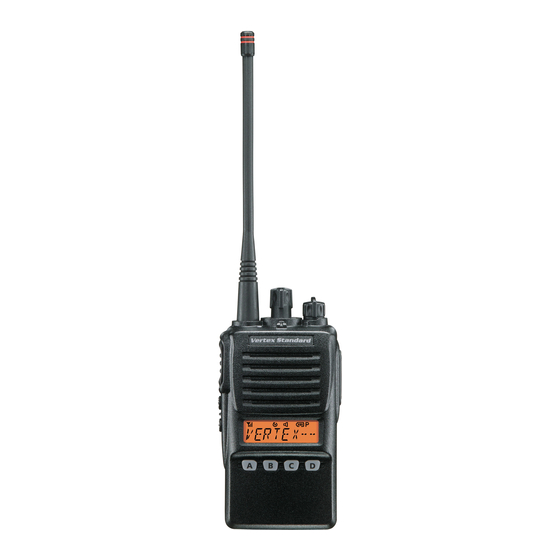
Controls & Connectors
LED Indicator
Monitor on (or Side 1, or 2 switch is activated: Non-LCD version)
Glows Green
Blinking Green
Busy Channel (or SQL off)
Glows Red
Transmitting
Battery Voltage is Low
Blinking Red
Yellow
Receiving a Selective Call
CH ( Channel ) Selector
Antenna
VOL/PWR Knob
Speaker
MIC/SP Jack
( External Mic/Earphone )
Push To Talk
( PTT ) Switch
Side 1 Switch
Microphone
Side 2 Switch
LCD
(LCD V
)
4 Key
(LCD V
Battery Pack Latch
E C 0 6 5 N 2 0 7
Accessories & Options
FNB-V96LIA
7.4 V 2300 mAh Li-Ion Battery Pack
FNB-V130LI-UNI
7.4 V 2300 mAh Li-Ion Battery Pack
VAC-300
Desktop Rapid Charger Set (CD-34+PA42, for FNB-V96LI)
VAC-6300
6-unit Multi Charger (for FNB-V96LI)
CD-58
Desktop Charger (for FNB-V130LI-UNI)
PA-55
AC Adapter (for CD-58)
VAC-6058
6-unit Multi Charger (for FNB-V130LI-UNI)
MH-37
Earpiece/Microphone
A4B
MH-45
Speaker/Microphone
B4B
MH-360S
Speaker/Microphone
MH-450S
Speaker/Microphone
VCM-2
Vehicle Charger Mount Adapter (for VAC-300)
DCM-1
Desktop Charger Mount Adapter (for VAC-300)
FVP-25
Encryption/DTMF pager Unit
FVP-35
Rolling Code Encryption Unit
FVP-36
Voice Inversion Encryption Unit
VME-100
MDC1200
®
/GE-Star
®
ANI Encoder Unit
ATU-6A
Rubber Antenna 400-430 MHz
ATU-6B
Rubber Antenna 420-450 MHz
ATU-6C
Rubber Antenna 440-470 MHz
ATU-6D
Rubber Antenna 450-485 MHz
ATU-6F
Rubber Antenna 485-520 MHz
ATV-6XL
Rubber Antenna 134-174 MHz (Untuned)
ATV-8A
Rubber Antenna 134-151 MHz
ATV-8B
Rubber Antenna 150-163 MHz
ATV-8C
Rubber Antenna 161-174 MHz
CLIP-17E
Swivel Belt Clip
CLIP-18
Belt Clip
LCC-350
Leather Case
CE86
Programming Software
FIF-12
USB Programming Interface
CT-27
Radio to Radio Programming Cable
CT-106
PC Programming Cable (for FIF-12)
Operating Temperature Range
Operation:
USA/EXP versions: –30 °C to +60 °C (–22 °F to +140 °F)
European version: –25 °C to +55 °C (–13 °F to +131 °F)
Battery Charging:
+10 °C to +40 °C (+50 °F to +104 °F)
Before You Begin
B
P
I
R
ATTERY
ACK
NSTALLATION AND
EMOVAL
To install the battery, hold the transceiver with your left
hand, so your palm is over the speaker and your
thumb is on the top of the belt clip. In-
sert the battery pack into the bat-
tery compartment on the back
of the radio while tilting the
Belt Clip outward, then push
the bottom side of the battery
pack until the battery pack
Locks with the Battery Pack
Latch.
To remove the battery, turn the radio off and remove any protective cases. Slide
the Battery Pack Latch on the bottom of the radio, then slide the battery down-
ward and out from the radio while holding the Belt Clip.
Caution!
Do not attempt to open any of the rechargeable Lithium-Ion packs, as they
could explode if accidentally short-circuited.
L
B
I
OW
ATTERY
NDICATION
As the battery discharges during use, the voltage gradually becomes lower. When
the battery voltage becomes to low, substitute a freshly charged battery and re-
charge the depleted pack. When the battery voltage is low, the LED indicator on the
top of the radio will blink red and "Battery Indicator" on the LCD will blink on the
LCD version. Furthermore, if your Dealer sets the "Low Battery Alert" feature into
the transceiver, an alert beeper will sound when the battery voltage is low.
)
I
N
MPORTANT
OTICE
Please follow these cautions to prevent hearing damage:
Always adjust the audio level of the transceiver to the minimum before
connecting the Earpiece/Headset to the transceiver.
Use the Earpiece/Headset at as low a volume as possible for existing
conditions.
Slowly adjust the VOL/PWR knob when increasing the audio level.
This Radio has been tested and complies with the Federal Communications
Commission (FCC) RF exposure limits for Occupational Use/Controlled ex-
posure environment. In addition, it complies with the following Standards and
Guidelines:
FCC 96-326, Guidelines for Evaluating the Environmental Effects of Ra-
dio-Frequency Radiation.
FCC OET Bulletin 65 Edition 97-01 (1997) Supplement C, Evaluating
Compliance with FCC Guidelines for Human Exposure to Radio Frequency
Electromagnetic Fields.
ANSI/IEEE C95.1-1992, IEEE Standard for Safety Levels with Respect to
Human Exposure to Radio Frequency Electromagnetic Fields, 3kHz to 300
GHz.
ANSI/IEEE C95.3-1992, IEEE Recommended Practice for the Measure-
ment of Potentially Hazardous Electromagnetic Fields-RF and Microwave.
WARNING: This radio generates RF electromagnetic energy during
transmit mode. This radio is designed for and classified as Occupa-
tional Use Only, meaning it must be used only during the course of employ-
ment by individuals aware of the hazards, and the ways to minimize such haz-
ards. This radio is not intended for use by the General Population in an uncon-
trolled environment.
CAUTION: To ensure that your expose to RF electromagnetic energy
is within the FCC allowable limits for occupational use, always adhere
to the following guidelines:
Please read this manual carefully to become familiar with the features
of this transceiver.
Do not transmit the radio without an antenna connected.
This radio is NOT approved for use by the general population in an
uncontrolled environment. This radio is restricted to occupational use,
work related operations only where the radio operator must have the
knowledge to control its RF exposure conditions.
When transmitting, hold the radio in a vertical position with its micro-
phone 1 to 2 inches (2.5 to 5 cm) away from your mouth and keep the
antenna at least 1 inch (2.5cm) away from your head and body.
The radio must be used with a maximum operating duty cycle not
exceeding 50 %, in typical Push-to-Talk (PTT) configurations. DO NOT
transmit for more than 50 % of total radio use time (50 % duty cycle).
P
S
RELIMINARY
TEPS
Install a charged battery pack onto the transceiver, as described previously.
Push the bottom side
of the battery pack
Screw the supplied antenna onto the Antenna jack. Never attempt to operate this
transceiver without an antenna connected.
If you have a Speaker/Microphone, we recommend that it not be connected
until you are familiar with the basic operation of the VX-350.
O
Q
S
PERATION
UICK
TART
Turn the top panel's VOL/PWR knob clockwise to
turn on the radio on.
Turn the top panel's CH selector knob to choose the
desired operating channel.
Rotate the VOL/PWR knob to set the volume level.
If no signal is present, press and hold in the Pro-
grammable key assigned to "SQL OFF" for more
than one second; background noise will now be
heard, and you may use this to set the VOL/PWR
knob for the desired audio level.
Press and hold in the Programmable key assigned
to "SQL OFF" for more than one second (or press
the key twice) to quiet the noise and resume normal
(quiet) monitoring.
SAFETY TRANING INFORMATION
Transmitting more than 50 % of the time can cause FCC RF exposure
compliance requirements to be exceeded.
To keep the Body Worn configuration with the Vertex Standard CLIP-
18 belt-clip, reduce the maximum operating duty cycle still more.
The radio is transmitting when the red LED on the top of the radio is
illuminated. You can cause the radio to transmit by pressing the PTT
button.
When operate the radio with the Vertex Standard CLIP-18 belt-clip,
make the transmission time as short as possible, to keep the Body Worn
configuration.
Always use the FNB-V96LIA or FNB-V130LI-UNI Lithium-Ion Bat-
tery.
Perform the battery charging where the ambient temperature range
+10 °C to +40 °C. Charge out of this range could cause damage to the
battery pack.
Battery Pack shall not be exposed to excessive heat such as sunshine,
fire or the like.
Always use Vertex Standard authorized accessories.
Vertex Standard shall not be liable for any damage or accidents such
as fire, leakage or explosion of batteries, etc., caused by the malfunc-
tion of non-Vertex Standard accessories.
The information listed above provides the user with the information needed to
make him or her aware of RF exposure, and what to do to assure that this radio
operates with the FCC RF exposure limits of this radio.
Electromagnetic Interference/Compatibility
During transmissions, this radio generates RF energy that can possibly
cause interference with other devices or systems. To avoid such interfer-
ence, turn off the radio in areas where signs are posted to do so.
Do not operate the transmitter in areas that are sensitive to electromag-
netic radiation such as hospitals, health care facilities, aircraft, and blast-
ing sites.
FCC License Information
This radio operates on communications frequencies which are subject to
FCC (Federal Communications Commission) Rules and Regulations. FCC
Rules require that all operators using Private Land Mobile radio frequen-
cies obtain a radio license before operating their equipment.
Operation
To transmit, monitor the channel and make sure it is clear.
To transmit, press and hold in the PTT switch. Speak
into the microphone area of the front panel grille
(lower right-hand corner) in a normal voice level.
To return to the Receive mode, release the PTT
switch.
Do not transmit the radio without an antenna con-
nected.
If a Speaker/Microphone is available, remove the plastic cap and its two mount-
ing screws from the right side of the transceiver, then insert the plug from the
Speaker/Microphone into the MIC/SP jack; secure the plug using the screws
supplied with the Speaker/Microphone. Hold the speaker grille up next to your
ear while receiving. To transmit, press the PTT switch on the Speaker/Micro-
phone, just as you would on the main transceiver's body.
Note:Save the original plastic cap and its mounting screws. They should
be re-installed when not using the Speaker/Microphone.
Display Icons & Indicators
LCD Version
: This channel is in the "Scan" List
: "Priority Scan" is activated
"Call" Indicator
"Dual Watch" is activated
Receiver Monitor
Low Power Transmit Mode
"Talk-Around" is enabled
"Encryption" is enabled
Battery Indicator
RSSI Indicator
Priority Channel indication
8 Character Alpha-numeric Display
This device complies with Part 15 of the FCC rules. Operation is subject to
the condition that this device does not cause harmful interference.
N
!
OTICE
There are no owner-serviceable parts inside the transceiver. All service
jobs must be referred to an authorized VERTEX STANDARD Service
Representative. Consult your Authorized VERTEX STANDARD Dealer
for installation of optional accessories.
I
N
N
A
MPORTANT
OTICE FOR
ORTH
MERICAN
R
406 MH
G
EGARDING
Z
UARD
The U.S. Coast Guard and National Oceanographic and Atmospheric Ad-
ministration have requested the cooperation of the U.S. Federal Communi-
cations Commission in preserving the integrity of the protected frequency
range 406.0 to 406.1 MHz, which is reserved for use by distress beacons.
Do not attempt to program this apparatus, under any circumstances, for
operation in the frequency range 406.0 - 406.1 MHz if the apparatus is to
be used in or near North America.
Warning - Frequency band 406 - 406.1 MHz is reserved for use ONLY
as a distress beacon by the US Coast Guard and NOAA. Under no
circumstance should this frequency band be part of the
preprogrammed operating frequencies of this radio.
D
E
ISPOSAL OF YOUR
LECTRONIC AND
E
E
LECTRIC
QUIPMENT
Products with the symbol (crossed-out wheeled bin) cannot be disposed as
household waste.
Electronic and Electric Equipment should be recycled at a
facility capable of handling these items and their waste
byproducts.
In EU countries, please contact your local equipment sup-
plier representative or service center for information about
the waste collection system in your country.
U
SERS
B
AND
Advertisement
Table of Contents

Subscribe to Our Youtube Channel
Related Manuals for Vertex Standard VX-350 Series


Summary of Contents for Vertex Standard VX-350 Series
- Page 1 Do not attempt to program this apparatus, under any circumstances, for ment by individuals aware of the hazards, and the ways to minimize such haz- Vertex Standard shall not be liable for any damage or accidents such ATU-6C Rubber Antenna 440-470 MHz operation in the frequency range 406.0 - 406.1 MHz if the apparatus is to...
- Page 2 When your radio is paged by a station bearing a tone sequence which matches The VX-350 series includes an “Emergency” feature, which may be useful, if you The scanner will search the channels, looking for active ones; it will pause each Lamp have someone monitoring on the same frequency as your transceiver’s channel.
Need help?
Do you have a question about the VX-350 Series and is the answer not in the manual?
Questions and answers