Table of Contents
Advertisement
Quick Links
Advertisement
Table of Contents

Summary of Contents for Dveo Futura II ASI+IP
- Page 1 Futura II ASI+IP™ Manual May 19, 2014 For sales information and technical support contact: Communitek Video Systems, Inc 545 West 45th Street, 9th Floor New York, NY 10036 Phone: 212-967-1774 Fax: 206-350-8140 dveosupport@communitekvideo.com http://www.communitekvideo.com...
-
Page 2: Before Using
Before Using .. Before using this device, please read this manual carefully from the beginning to the end to fully exercise its performance and ensure longer service life through the correct use of the products. About Warranty .. The product warranty is included in the rear part of this users manual. We carry out free warranty repair system for one year from the date of purchase of the product based on our warranty policy. -
Page 3: Before Starting
Before starting .. This manual is a guidebook with regard to the method of use and composition of the MPEG-2/4 AVC HD Encoder (Hereinafter “Device”). Before using this device, please be sure to read this manual thoroughly. After unpacking the package, please check various components and, if you have any questions or inquiries, please contact our agent from whom you have purchased the device or our company. - Page 4 Release History Edit Date Approved by Description Oct . 21 , 2011 First Version May 15, 2012 Official release June 20, 2012 Update Web NMS...
-
Page 5: Free Maintenance
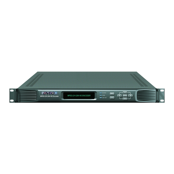
Free Maintenance In case any problems occur with this product, you are eligible to receive services for the replacement of the parts or exchange of the product. The period of maintenance may be extended by a separate contract. For more information in this regard, please contact your dealer from whom you have purchased the product or our company. - Page 7 ① VFD Display Displays current status of the device, main menu and 5 different modes of the device function setting screen. Press ⑤ MENU button and ⑥ ESC button simultaneously to switch the device setting screen. ② HD-SDI LED Lights up when the HD/SD-SDI signal of digital mode is normally inputted. ③...
- Page 8 ① Cooling Fan ② Power Switch and AC Power Input Terminal Use power AC 110~220V, 50/60Hz. The input power of the device can be turned On/Off by using power switch. ③ SNMP Connection Terminal (option) The status of the device can be monitored and controlled in remote area with LAN system using RJ-45 connection jack.
- Page 9 - Satellite Receiver Camera for - Character generator broadcasting Blu-ray Player - CCTV camera image SIGNAL SYNCER R LEFT RIGHT 8VSB REMODULATOR RF OUT MENU DRM-1902ML DOWN Ac power input DVB-ASI in/output Ethernet IP Stream SNMP Server or web browser control ※...
- Page 10 1-1. Start up ① Connect the AC power to the power input terminal on the back side and turn the power switch ON. ② Booting While connecting power, the [Picture 1-1] below will be displayed on the screen and booting of the device will be accomplished.
- Page 11 1-2. Shut down ① In the state main screen is displayed as shown in the [Picture 1-2], turn the power switch on the back side OFF. ② Press the MENU button to move to the upper menu from all menu screen. Also, even without pressing the MENU button after operation, it will automatically move to the main screen after a certain time has elapsed.
- Page 12 2-1. Setting of Video Input Signal ① When the MENU button and the ESC button are pressed simultaneously in the main screen [Picture 1-2], a menu screen shown in the [Picture 2-1] will be displayed. [Picture 2-1] Menu Screen [Picture 2-2] Sub Menu Screen [Picture 2-3] Setting of Video Input Signal ②...
- Page 13 2-2. Setting of IP Stream ① When the MENU button and the ESC button are pressed simultaneously in the main screen [Picture 1-2], a menu screen will be displayed as shown in the [Picture 2-4]. [Picture 2-4] Menu Screen [Picture 2-5] Sub Menu Screen Picture 2-6] Setting of IP Stream ②...
- Page 14 3-1. Setting of Video Encoding & Bit Rate ① When the MENU button and the ESC button are pressed simultaneously in the main screen [Picture 1-2], a menu screen will be displayed as shown in the [Picture 3-1]. [Picture 3-4] Video Encoder [Picture 3-1] Menu Screen [Picture 3-2] Sub Menu Screen ②...
- Page 15 3-2. Setting of Aspect Ratio ① When the MENU button and the ESC button are pressed simultaneously in the main screen [Picture 1-2], the menu screen shown in the [Picture 3-7] will be displayed. [Picture 3-7] Menu Screen [Picture 3-8] Sub Menu Screen Picture 3-9] Setting of Aspect Ratio ②...
- Page 16 3-3. Setting of Video GOP Type ① When the MENU button and the ESC button are pressed simultaneously in the main screen [Picture 1-2], the menu screen shown in the [Picture 3-10] will be displayed. [Picture 3-10] Menu Screen [Picture 3-11] Sub Menu Screen Picture 3-12] Setting of Video GOP Type ②...
- Page 17 3-4. Setting of Video Resolution and Video Frame Rate ① When the MENU button and the ESC button are pressed simultaneously in the main screen, [Picture 1-2] the menu screen shown in the [Picture 3-7] will be displayed. [Picture 3-13] Menu Screen [Picture 3-14] Sub Menu Screen Picture 3-15] Setting of Video Resolution ②...
- Page 18 4-1. Setting of Audio Encoder ① When the MENU button and the ESC button are pressed simultaneously in the main screen [Picture 1-2], the menu screen shown in the [Picture 4-1] will be displayed. [Picture 4-1] Menu Screen [Picture 4-2] Sub Menu Screen Picture 4-3] Setting of Audio Encoder ②...
- Page 19 4-2. Setting of Audio Bit rate ① When the MENU button and the ESC button are pressed simultaneously in the main screen [Picture 1-2], the menu screen shown in the [Picture 4-4] will be displayed. [Picture 4-4] Menu Screen [Picture 4-5] Sub Menu Screen Picture 4-6] Setting of Audio Bit rate ②...
- Page 20 4-3. Setting of Audio Channel ① When the MENU button and the ESC button are pressed simultaneously in the main screen [Picture 1-2], the menu screen shown in the [Picture 4-7] will be displayed. [Picture 4-7] Menu Screen [Picture 4-8] Sub Menu Screen Picture 4-9] Setting of Audio input CH ②...
- Page 21 4-4. Setting of Audio Signal Volume Level ① When the MENU button and the ESC button are pressed simultaneously in the main screen [Picture 1-2], the menu screen shown in the [Picture 4-10] will be displayed. [Picture 4-10] Menu Screen [Picture 4-11] Sub Menu Screen [Picture 4-12] Setting of Audio Signal Volume Level...
- Page 22 4-5. Setting of Audio Signal Delay Time ① When the MENU button and the ESC button are pressed simultaneously in the main screen [Picture 1-2], the menu screen shown in the [Picture 4-13] will be displayed. [Picture 4-13] Menu Screen [Picture 4-14] Sub Menu Screen Picture 4-15] Setting of Audio Delay ②...
- Page 23 4-6. Setting of Auto Gain Control (AGC) ① When the MENU button and the ESC button are pressed simultaneously in the main screen [Picture 1-2], the menu screen shown in the [Picture 4-16] will be displayed. [Picture 4-16] Menu Screen [Picture 4-17] Sub Menu Screen Picture 4-18] Setting of Auto Gain Control...
- Page 24 4-7. Setting of Audio PTM ① When the MENU button and the ESC button are pressed simultaneously in the main screen [Picture 1-2], the menu screen shown in the [Picture 4-19] will be displayed. [Picture 4-19] Menu Screen [Picture 4-20] Sub Menu Screen Picture 4-21] Setting of PTM ②...
- Page 25 4-8. Setting of Audio Mix ① When the MENU button and the ESC button are pressed simultaneously in the main screen [Picture 1-2], the menu screen shown in the [Picture 4-13] will be displayed. [Picture 4-22] Menu Screen [Picture 4-23] Sub Menu Screen Picture 4-24] Setting of Mix ②...
- Page 26 5-1. PSIP Setting ① When the MENU button and the ESC button are pressed simultaneously in the main screen [Picture 1-2], the menu screen shown in the [Picture 5-1] will be displayed. [Picture 5-1] Menu Screen [Picture 5-2] Sub Menu Screen [Picture 5-3 ] PSIP/PSI Mode setting ②...
-
Page 27: Pid Setting
5-2. PID Setting ① When the MENU button and the ESC button are pressed simultaneously in the main screen [Picture 1-2], the menu screen shown in the [Picture 5-6] will be displayed. [Picture 5-7] Menu Screen [Picture 5-8] Sub Menu Screen Picture 5-9 ] Setting of PID ②... -
Page 28: Network Setting
6-1. Network Setting ① When the MENU button and the ESC button are pressed simultaneously in the main screen [Picture 1-2], the menu screen shown in the [Picture 6-1] will be displayed. [Picture 6-2] Sub Menu Screen [Picture 6-3] Setting of TCP/IP Mode [Picture 6-1] Menu Screen ②... - Page 29 6-2. Setting of System Delay ① When the MENU button and the ESC button are pressed simultaneously in the main screen [Picture 1-2], the menu screen shown in the [Picture 6-8] will be displayed. [Picture 6-8] Menu Screen [Picture 6-9] Sub Menu Screen Picture 6-10] Setting of System Delay ②...
- Page 30 6-3. Setting of Total Bit rate ① When the MENU button and the ESC button are pressed simultaneously in the main screen [Picture 1-2], the menu screen shown in the [Picture 6-11] will be displayed. [Picture 6-11] Menu Screen [Picture 6-12] Sub Menu Screen [Picture 6-13] Total Bit rate Setting mode ②...
- Page 31 6-4. Checking of S/W Revision ① When the MENU button and the ESC button are pressed simultaneously in the main screen [Picture 1-2], the menu screen shown in the [Picture 6-14] will be displayed. [Picture 6-14] Menu Screen [Picture 6-15] Sub Menu Screen Picture 6-16] Firmware Version Check ②...
- Page 32 6-5. Setting of Initialization System Data ① When the MENU button and the ESC button are pressed simultaneously in the main screen [Picture 1-2], the menu screen shown in the [Picture 6-17] will be displayed. [Picture 6-17] Menu Screen [Picture 6-18] Sub Menu Screen [Picture 6-19] Init System Data ②...
- Page 33 7-1. Install This device is controlled over an Ethernet link by a computer running any standard Web browser (called the Web controller). A Web controller may be located anywhere convenient, limited only by the requirement that it have access to the subnet where the encoders are located. CAUTION: This device has two Ethernet connectors on the rear panel, one for control of the encoder and the other one for an IP output stream carrying encoded video and audio.
- Page 34 7-2. Searching IP of Device - Configuration Tool Insert the Setting CD into CD drive and then you can see the [Figure 7-1] when ‘WIZ-Web_V1_2.exe’ file is running. As [Figure 7-2] is shown, click on the ‘Search’ button and then confirm the F/W version, IP Address and Subnet Mask and Gateway.
- Page 35 7-3. Basic Configuration Tool ⓐ ⓒ ⓑ ⓓ ⓔ ⓕ ⓖ ⓗ ⓘ ⓙ ⓚ [Figure 7-4] Configuration Tool ⓐ Version : It displays firmware version. ⓑ Board List : If “Search” button is clicked, all the MAC address are displayed in the Board List. ⓒ...
- Page 36 7-4. Web NMS To access from a browser Start a browser (Internet Explorer, Firefox). Enter the IP address of encoder in the location / address field of your browser. The encoder’s Web NMS page appears in your browser. [Picture 7-5] Index page of Web Browser Control ①...
- Page 37 7-4-1.System Setting When the web NMS is running, you will see a simple graphical interface for viewing settings screen [Picture 6-6]. The tap delineate groups of controls for each type of task to be performed. Click on any of tabbed buttons and the screen below will change to match. Each of screen are described the following page.
- Page 38 7-4-2. Input / Output Setting user . Hello | LOGOUT DME-9624H | HD Encoder SYSTEM IN/OUTPUT VIDEO AUDIO PSIP INPUT / OUTPUT Information & Setting VIDEO INPUT HDMI AUDIO INPUT HDMI APPLY [Figure 7-7] Input /Output Tab Screen Ⓐ VIDEO INPUT : Pull down menu is as following. •...
- Page 39 7-4-3. Video Setting user . Hello | LOGOUT DME-9624H | HD Encoder SYSTEM IN/OUTPUT VIDEO AUDIO IPSIP VIDEO Information & Setting Video Encoder Type H.264 MPEG-2 Video Bit Rate [Measure : kbps, Range : 5 ~ 250] Video Resolution Mode AUTO MANUAL Video Resolution...
- Page 40 7-4-4. Audio Setting user . Hello | LOGOUT DME-9624H | HD Encoder SYSTEM IN/OUTPUT VIDEO AUDIO PSIP AUDIO Information & Setting Audio Encoder Type AC3(CE) Audio Bit Rate Kbps 1~99 Audio Volume Audio Auto Gain Audio Pass Through Audio Input Channel Channel 1&2 Audio Mix Stereo 1CH...
- Page 41 7-4-5. PSIP Setting user . Hello | LOGOUT DME-9624H | HD Encoder SYSTEM IN/OUTPUT VIDEO AUDIO PSIP PSIP Information & Setting TVCT Generate PSIP OFF Internal PSIP External PSIP TVCT Short Name TVCT TVCT CH APPLY [Figure 7-10] PSIP Tab Screen The IP Stream Tab screen is where you can configure TVCT Generate, short name, and CH.
- Page 42 7-4-6. PID Setting user . Hello | LOGOUT DME-9624H | HD Encoder SYSTEM IN/OUTPUT VIDEO AUDIO PSIP Information & Setting BASE PID 0x1ffb 0x0001 ~0x1FFE Video PID 0x0100 0x0001 ~0x1FFE Audio PID 0x0201 0x0001 ~0x1FFE PMT PID 0x0050 0x0001 ~0x1FFE APPLY [Figure 7-11] PID Tab Screen Ⓐ...
-
Page 43: Points To Be Checked
Make sure before reporting troubles Troubles Points to be checked Power does not IN • Check whether the power plug is accurately connected or, Front LCD, LED does not light up check the power switch on the back side. Power IN but device does not work •... - Page 44 Complete product Front view Rear view 1 : Signal 2 : GND 3 : Signal Assembly diagram Assembly method 1. Put cable into ④ -> ③ -> ②. 2. Connect the cable core wire by soldering on the connecting pin of ②. 3.
-
Page 45: Warranty
Computer Modules, Inc. Aircraft or Spacecraft Policy DVEO products are not authorized to be installed in, or used or contained within, any aircraft or spacecraft whatsoever without the expressed written approval of the president of...
Need help?
Do you have a question about the Futura II ASI+IP and is the answer not in the manual?
Questions and answers