Table of Contents
Advertisement
Quick Links
Advertisement
Table of Contents

Summary of Contents for E-castle EOS?9604
- Page 1 EOS960H DVR USER’s MANUAL RoHS Version20140620...
- Page 2 Important Safety Instructions Read and Keep these instructions Heed all warnings Follow all the instructions Do not use this apparatus near water and Clean only with dry cloth Do not install near any heat sources such as radiators, heat registers, or other apparatus that produce heat Protect the power cord from being walked on or pinched particularly at plugs, convenience receptacles, and the point where they exit from the apparatus. Unplug this apparatus. When a cart is used, use caution when moving the cart/apparatus combination to avoid injury from tip‐over. TO REDUCE THE RISK OF ELECTRIC SHOCK, DO NOT REMOVE. NO USER‐SERVICEABLE PARTS ARE INSIDE. REFER SERVICING TO QUALIFIED SERVICE PERSONNEL. The lightning flash with an arrowhead symbol within an equilateral triangle is intended to alert the user to the presence of uninsulated “ dangerous voltage” within the product’s enclosure that may be of sufficient magnitude to constitute a risk of electric shock to persons. The exclamation point within an equilateral triangle is intended to alert the user to presence of important operating and maintenance (Servicing) instructions in the literature accompanying the appliance ...
- Page 3 FEATURES This 960H DVR allows users to have video surveillance both in live and playback. H.264 compression HDMI, VGA outputs, and composite out(Live or Spot) Individual channel setup for recording & network stream (resolution/frame rate) Event text + image notification to FTP server and E‐mail address Easy network : UPNP (Universal plug & play) support User control : Up to 20 users can be generated with various access authority Calendar/Time search & Thumbnail search & POS search Smart phone application (Live, PTZ, Search) E‐SATA is supported Mirror and auto‐backup is supported BNC programmable spot outs Up to 4 internal SATA HDD Optical Driver is supported ‐ 3 ‐ ...
- Page 4 INDEX 1. Product introduction 1.1. Packing ∙∙∙∙∙∙∙∙∙∙∙∙∙∙∙∙∙∙∙∙∙∙∙∙∙∙∙∙∙∙∙∙∙∙∙∙∙∙∙∙∙∙∙∙∙∙∙∙∙∙∙∙∙∙∙∙∙∙∙∙∙∙∙∙∙∙∙∙∙∙∙∙∙∙∙∙∙ 1.2. Front ∙∙∙∙∙∙∙∙∙∙∙∙∙∙∙∙∙∙∙∙∙∙∙∙∙∙∙∙∙∙∙∙∙∙∙∙∙∙∙∙∙∙∙∙∙∙∙∙∙∙∙∙∙∙∙∙∙∙∙∙∙∙∙∙∙∙∙∙∙∙∙∙∙∙∙∙∙ 1.3. Rear ∙∙∙∙∙∙∙∙∙∙∙∙∙∙∙∙∙∙∙∙∙∙∙∙∙∙∙∙∙∙∙∙∙∙∙∙∙∙∙∙∙∙∙∙∙∙∙∙∙∙∙∙∙∙∙∙∙∙∙∙∙∙∙∙∙∙∙∙∙∙∙∙∙∙∙∙∙ 2. Installation 2.1. Installing HDD ∙∙∙∙∙∙∙∙∙∙∙∙∙∙∙∙∙∙∙∙∙∙∙∙∙∙∙∙∙∙∙∙∙∙∙∙∙∙∙∙∙∙∙∙∙∙∙∙∙∙∙∙∙∙∙∙∙∙∙∙∙∙∙∙∙∙∙∙∙∙∙∙∙∙∙∙∙ 2.2. How to connect devices to Product ∙∙∙∙∙∙∙∙∙∙∙∙∙∙∙∙∙∙∙∙∙∙∙∙∙∙∙∙∙∙∙∙∙∙∙∙∙∙∙∙∙∙∙∙∙∙∙∙∙ 2.2.1. Front ∙∙∙∙∙∙∙∙∙∙∙∙∙∙∙∙∙∙∙∙∙∙∙∙∙∙∙∙∙∙∙∙∙∙∙∙∙∙∙∙∙∙∙∙∙∙∙∙∙∙∙∙∙∙∙∙∙∙∙∙∙∙∙∙∙∙∙∙∙∙∙∙∙∙∙∙∙ 12 2.2.2. Rear ∙∙∙∙∙∙∙∙∙∙∙∙∙∙∙∙∙∙∙∙∙∙∙∙∙∙∙∙∙∙∙∙∙∙∙∙∙∙∙∙∙∙∙∙∙∙∙∙∙∙∙∙∙∙∙∙∙∙∙∙∙∙∙∙∙∙∙∙∙∙∙∙∙∙∙∙∙ 2.2.3. Connection of main devices ∙∙∙∙∙∙∙∙∙∙∙∙∙∙∙∙∙∙∙∙∙∙∙∙∙∙∙∙∙∙∙∙∙∙∙∙∙∙∙∙∙∙∙∙∙∙∙∙∙∙∙∙∙∙ 3.
-
Page 5: Table Of Contents
4. MENU 4.1. How to open MENU ∙∙∙∙∙∙∙∙∙∙∙∙∙∙∙∙∙∙∙∙∙∙∙∙∙∙∙∙∙∙∙∙∙∙∙∙∙∙∙∙∙∙∙∙∙∙∙∙∙∙∙∙∙∙∙∙∙∙∙∙∙∙∙∙∙∙∙∙∙∙ 4.2. Set up ∙∙∙∙∙∙∙∙∙∙∙∙∙∙∙∙∙∙∙∙∙∙∙∙∙∙∙∙∙∙∙∙∙∙∙∙∙∙∙∙∙∙∙∙∙∙∙∙∙∙∙∙∙∙∙∙∙∙∙∙∙∙∙∙∙∙∙∙∙∙∙∙∙∙∙∙∙∙∙∙ 4.2.1. Display ∙∙∙∙∙∙∙∙∙∙∙∙∙∙∙∙∙∙∙∙∙∙∙∙∙∙∙∙∙∙∙∙∙∙∙∙∙∙∙∙∙∙∙∙∙∙∙∙∙∙∙∙∙∙∙∙∙∙∙∙∙∙∙∙∙∙∙∙∙∙∙∙∙∙∙∙∙∙∙∙ 4.2.2. Camera ∙∙∙∙∙∙∙∙∙∙∙∙∙∙∙∙∙∙∙∙∙∙∙∙∙∙∙∙∙∙∙∙∙∙∙∙∙∙∙∙∙∙∙∙∙∙∙∙∙∙∙∙∙∙∙∙∙∙∙∙∙∙∙∙∙∙∙∙∙∙∙∙∙∙∙∙∙∙∙ 4.2.3. Record ∙∙∙∙∙∙∙∙∙∙∙∙∙∙∙∙∙∙∙∙∙∙∙∙∙∙∙∙∙∙∙∙∙∙∙∙∙∙∙∙∙∙∙∙∙∙∙∙∙∙∙∙∙∙∙∙∙∙∙∙∙∙∙∙∙∙∙∙∙∙∙∙∙∙∙∙∙∙∙ 4.2.4. Event ∙∙∙∙∙∙∙∙∙∙∙∙∙∙∙∙∙∙∙∙∙∙∙∙∙∙∙∙∙∙∙∙∙∙∙∙∙∙∙∙∙∙∙∙∙∙∙∙∙∙∙∙∙∙∙∙∙∙∙∙∙∙∙∙∙∙∙∙∙∙∙∙∙∙∙∙∙∙∙ 28 4.2.5. Storage ∙∙∙∙∙∙∙∙∙∙∙∙∙∙∙∙∙∙∙∙∙∙∙∙∙∙∙∙∙∙∙∙∙∙∙∙∙∙∙∙∙∙∙∙∙∙∙∙∙∙∙∙∙∙∙∙∙∙∙∙∙∙∙∙∙∙∙∙∙∙∙∙∙∙∙∙∙∙∙ 4.2.6. Network ∙∙∙∙∙∙∙∙∙∙∙∙∙∙∙∙∙∙∙∙∙∙∙∙∙∙∙∙∙∙∙∙∙∙∙∙∙∙∙∙∙∙∙∙∙∙∙∙∙∙∙∙∙∙∙∙∙∙∙∙∙∙∙∙∙∙∙∙∙∙∙∙∙∙∙∙∙∙∙ 33 4.2.7. System ∙∙∙∙∙∙∙∙∙∙∙∙∙∙∙∙∙∙∙∙∙∙∙∙∙∙∙∙∙∙∙∙∙∙∙∙∙∙∙∙∙∙∙∙∙∙∙∙∙∙∙∙∙∙∙∙∙∙∙∙∙∙∙∙∙∙∙∙∙∙∙∙∙∙∙∙∙∙∙ 36 4.3. Search ∙∙∙∙∙∙∙∙∙∙∙∙∙∙∙∙∙∙∙∙∙∙∙∙∙∙∙∙∙∙∙∙∙∙∙∙∙∙∙∙∙∙∙∙∙∙∙∙∙∙∙∙∙∙∙∙∙∙∙∙∙∙∙∙∙∙∙∙∙∙∙∙∙∙∙∙∙∙ 40 4.3.1. - Page 6 1. Introduction ‐ 6 ‐ ...
-
Page 7: Packing
1.1. Packing When you first open the product, please check out whether there are all contents as follows. If any of these items is missing or damaged, please contact your supplier immediately before using the product. As Optional Mouse and HDD Drive could be included or excluded in packing according to seller’s option, they must be checked before DVR is used. DVR Product Remote control & Battery(AAA) ... -
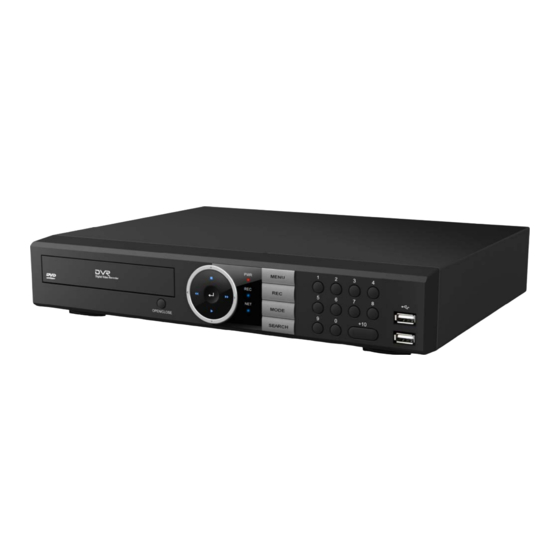
Page 8: Front
1.2 Front DVD Writer DVD Writer Door Direction Move the Curosor in MENU Select Items For Playback Stop playback ■ Fast backward playback ◀◀ Step backward(Playback the previous frame in pause mode) Play and pause ▶I Fast forward playback ▶▶... -
Page 9: Rear
1.3 REAR 4 Channel DVR 8 Channel DVR 16 Channel DVR e-SATA External SATA Audio Out Audio output (RCA) Audio In Audio Input Connection (RCA) CAMERA in Video Camera Connection (BNC) SPOT /TV Live or SPOT out (BNC) HDMI HDMI output (HDMI type-C) VGA or LCD mitor (D-SUB 15p) Ethernet Cable Modem, Ethernet 10/100 Base-T (RJ-45) - Page 10 2. Installation ‐ 10 ‐ ...
-
Page 11: Installing Hdd
2.1. Installing HDD If HDD is not installed in DVR which you purchased, Please install HDD first inside it. four(4) internal HDD or one DVD & two HDD can be installed inside DVR. Please prepare cables and screws before installation. Please be careful not to be harmed by sharp edges of the products Please follow the below steps to install HDD inside DVR without difficulty. (1) Loosen screws on both sides and back to (2) Lift the end of top cover and pull out from detach the product cover. product. (3) Loosen screws of HDD bracket to detach from Restore HDD bracket to product and product. -
Page 12: How To Connect Devices To Product
2.2. How to connect Devices to product 2.2.1. Front 2.2.2. Rear .. ... ... - Page 13 3) Audio, Sensor, Alarm, and RS‐485 Please refer the previous page to connect devices to DVRs. Sensor device should be connected to S and G port. Alarm devices should be connected to A and G port. The type of Alarm (NC/NO) should be used selected in DVR MENU in accordance with alarm device. PTZ camera or keyboard control is connected to RS‐485(+,‐) port. Device doesn’t work when the polarity is wrong. Please be careful not to connect it to different polarity. 4) Video Out 3 kinds of Video (HDMI, VGA, BNC) are supported by DVRs. BNC is used for Live or Spot When Video out is connected to VGA port of Monitor, the monitor 1920 * 1080 or 1024 *768. Please check CONFIG S/W in rear side for HD(1920*1080) or XGA(1024*768) 5) E‐SATA Some brand of E‐SATA HDD Rack are not supported. Please ask or check whether HDD Rack is supported or not before usage. 6) USB Port USB Mouse, USB memory stick, USB HDD, or external ODD drive can be connected to USB port. External USB ODD doesn’t support multisession format, please check the CD capacity and backup data capacity first before you backup recorded data to CD. 7) Ethernet Port It is used to connect DVR to PC or internet . ...
- Page 14 3. How to start DVR ‐ 14 ‐ ...
-
Page 15: Remote Control
PLEASE MAKE SURE THAT THE HDD MUST BE INSTALLED AT FIRST FOR RECORDING BEFORE USING DVR. 3.1. Turning on There is no any power switch, therefore please connect all devices to DVR before DVR is turned on. By connecting the Adaptor included in Box to DVR, it is turned on. 3.2. Remote control 1) REC : Instant record button 2) DVR ID : selecting controlled DVR 3) Number button : Input channel number 4) AUDIO : Audio ON / Mute 5) BACKUP : Access directly to backup menu 6) MENU : Access to main menu ... -
Page 16: Mouse
3.3. MOUSE A mouse is used after connected to USB terminal in front or rear without installation. Click on left button Popup Login window/Selecting Icons/its values Selecting sub‐menu in setup menu and values in each menu Click on right button Popup Main Menu/Back from menu to live mode Double click on left button Change one ch to multi ch or multi ch to one ch mode. 3.4. Key Operation 3.4.1. MENU Function Remote control Front Key MOUSE Popup Menu Press <MENU> Key Press <MENU> Key Click on right button Move : ▲,▼,◀,▶ Move & ... -
Page 17: Sequence Mode
3.4.3. OSD It is used to appear or disappear information of cameras and ICONS in screen. Press <OSD> key in remote control, or click <OSD> in Main menu to use OSD function. 3.4.4. Sequence Mode If you press SEQ button in Full screen split, screen will rotate automatically Default value of cannel rotating interval is 2 seconds, which can be changed from 0 to 99 second . The”0” interval time skip the selected channel without display. 3.4.5. Channel Selection Function Remote control Front Key MOUSE Channel Selection Press Mode, or Numeric key Press MODE key click in screen 1 channel mode ... -
Page 18: Screen Layout
Please enter default password (0000) in password window, and click OK icon and then LOGIN icon. It is ready to be accessable to DVR. If you want to change password, please refer the [MENU‐SETUP‐SYSTEM‐USER]. 3.6. Screen Layout You can see the below items according to your selection on function. 3.6.1. Icons in Live Mode In Live display mode, icons will be indicated to notify the system mode or status. Below are the icon categories, which are indicated on the monitor. Icon for system Icon for each channel Selects specific 1ch with full screen When Motion Detected Screen‐Division mode When Sensor Activated Check auto‐backup with external USB Channel with audio connected HDD (status, capacity) ... -
Page 19: Icons In Playback Mode
3.6.2. Icons in playback mode In search mode, the status will be shown in the upper side of screen. You can control playback using the buttons. ICON Name Description This icon shows the current status in playback. Current status If you select ▶, the mark will be ▶, Ex) If you select FF (fast‐forward), ▶▶ will be shown. ... - Page 20 4. MENU ‐ 20 ‐ ...
-
Page 21: How To Open Menu
4.1. How to open MENU Press MENU button on front keys or remote control, or click on the right button of mouse in any position. Before access to main menu, DVR asks you login ID and password. When you first start DVR, input ADMIN for ID and 0000 for password as Initial ID & password are ADMIN & 0000 respectively. Main menu consists of following ICONS : Setup, Search, Audio, Spot, Backup, Log view, REC, OSD and Log out. 4.2. Set up The followings are contenst of sub‐menu. DISPLAY RECORD STORAGE SYSTEM CAMERA EVENT HDD FORMAT OSD GENERAL PARAMETER MOTION CONFIG HDD SMART ... -
Page 22: Display
4.2.1. Display Configuration related to OSD and Sequence patterns of main/spot monitors can be set. 4.2.1.1. OSD OSD items that displays on monitor and language are selected. Camera Name Show camera name on screen. Camera Number Show each camera numbers on the screen Camera Border Show outline of channel Language Select OSD language OSD HIDE ALL, Time bar, Icon AUTO HIDE ON : Hide ALL, time bar or icon Time out automatically after selected time‐out. ... -
Page 23: Camera
4.2.1.3. SEQ‐QUAD SEQUENCE : Set Quad‐ channel and dwell time by second for main video out. CH Sequence camera numbers. It can’t be changed. TIME Diplaying time on the channel from 0 to 99 : 0 means not to display the channel DEFAULT The times are defaulted factory option. Default value is 3 second 4.2.2. Camera General camera configurations such as camera name, Private zone can be made. 4.2.2.1. General NAME Input name of each camera using virtual keyboard. ... - Page 24 4.2.2.2. Private Zone To protect privacy, User can choose the zone which is not seen for each camera. Camera : select the channel that user want to adjust private zone Click on left button of mouse to select the zone. Separarted zone can’t be selected All users can’t see the selected private zone Remark : The selected zone can not be seen in both live mode and recorded data 4.2.2.3. PTZ ID Input ID of connected PTZ camera PROTOCOL Select protocol type of PTZ camera ...
- Page 25 ④ Click Advance icon or Press ENTER Key in remote controller to save. ⑤ Click any other position on screen by mouse or press MENU Key to cancel. If you like to cancel the setting, please click the CLE icon of the channel will be cleared. If you click “CLEAR ALL” button, all value of channels will be cleared. NOTE : Before using this function, please make sure that camera supports preset. Total 64 preset points can be saved to each channel. You can enter position name to each saved preset position. 4.2.2.5. TOUR CAMERA Select camera to set up scan point LIST Create another SCAN list reset PRESET Select desired preset potion CLEAR ALL Cancel all saved scan points SEC Dwelling time at the position NOTE In SCAN point menu, you can set up PTZ tour route(SCAN‐LIST) using saved PRESET position. ...
- Page 26 4.2.2.7. POS DVR support POS type terminal by USB serial. DVR support upto 4 POS interface. 4.2.2.7.1 POS SETUP START CHARACTER Start code of analyzed from POS equipment END CHARACTER End code of analyzed from POS equipment LINE BREAK Line deliminator (CR, LF, CR/LF) default is CR/LF BAUDRATE Communication Baud rate with POS equipment. Default is “1200” DATABIT Communinication Data Bit per characters. Default is “8” STOP BIT Communication Stop bit. Fixed as “1” PARITY Communication Parity bit. Fixed as “NONE” 4.2.2.7.2 POS OSD CH Interworking Camera number with POS equipment. DISPLAY Maximum displayed line numbers for POS data display. LINE ...
-
Page 27: Record
4.2.3. RECORD Recording setup such as parameter, schedule and pre/post recording can be made in RECORD menu 4.2.3.1. PARAMETER Resolution Recording resolution can be changed by “960H” “D1” “CIF” EVENT Select the recording picture quality and frame rate for EVENT occasions. Event occasions mean when motion is detected or alarm is triggered. Each channel can have separate picture quality and frame rate. CONTINUOUS Select the recording picture quality and frame rate for continuous recording Each channel can have separate picture quality and frame rate The frame rate in CONTINOUS cannot exceed that of Event mode. If frame rate of EVENT is set up as 8, and that of CONTINUOUS mode cannot exceed 8. ALL Apply the same picture quality & frame rate for all channels. ... -
Page 28: Event
REC OFF No record, just monitor during selected hours. CONTINUOUS REC DVR records continuously during selected days and hours. EVENT REC DVR records only when Motion/Sensor/Video Loss is triggered during selected hours. CONTINUOUS+EVENT REC DVR records continuously or by events during selected days and hours. If no event, it will record video as continuous mode and If event, it will record video as event mode as you set. NOTE: Recording schedule can be set by hour. The time in the first column of each line means one hour 4.2.3.3. GENERAL OVERWRITE When HDD gets full, the oldest record data will be erased and replaced (overwritten) by new data. : ON is for [use OVERWRITE], OFF is for [not use OVERWRITE] If it is set OFF, DVR stops recording when HDD gets full. ... - Page 29 4.2.4.1. MOTION CAMERA Select camera for motion setup SENSITIVITY Adjust motion sensitivity from 0~9 The higher number, the more sensitive detection ALARM‐OUT Select alarm‐out number which will be triggered when motion is detected. RECORDCH Select channels which will record when motion is detected. BUZZER Set ON/OFF for buzzer when motion is detected NIGHT Set separate sensitivity for day and for night. This option can MODE be used in order to avoid false motion event caused by camera noise at night. SET ALL All area (8x8 Grid) will be enabled for motion detection. CLEAR ALL All area (8x8 Grid) will be disabled for motion detection. 4.2.4.2. SENSOR TYPE Select NO(Normal open)/NC(Normal closed) RECORD Select camera channels which will record when sensor is activated. ALARM‐OUT Select alarm‐out number which will be triggered when sensor is activated. ...
- Page 30 EVENT E‐MAIL Select ALL time or SCHEDULE for email notification Check the box then DVR sends image as well as text when events occur. IMAGE EVENT TYPE Select event type from MOTION, POWER ON, SENSOR, HDD ERROR, VLOSS DVR sends email with this name. SENDER ID DVR Input up to 2 email addresses receive email. E‐MAIL ADDRESS Example: anyone@gmail.com SECURE TYPE NORMAL: Standard email transfer, Port 21 SSL(485): Secure email transfer, Port 485 TLS(587): Secure email transfer, Port 587 SERVER NAME In case of using SSL or TLS, input SMTP server name. ID/PASSWORD In case of using SSL or TLS, input ID and password of SMTP server. NOTE: You can find SMTP server information usually from POP3/SMTP, IMAP/SMTP setup menu of the server. Otherwise, you need to ask the server manager EXAMPLE: If you have an account in Gmail, Input smtp.gmail.com in SERVER NAME and ID/PASSWORD of your Gmail account. If normal is selected, you don’t need to input in SERVER NAME and ID/PASSWORD. EXAMPLE: Email message ...
-
Page 31: Storage
. E‐MAIL/ALARM/FTP SCHEDULE 4.2.4.6. Make a schedule for e‐mail transfer, alarm‐out and ftp transfer for events. Schedule can be arranged by day and by hour. Only during checked day and time, e‐mail will be sent and alarm out will be activated and ftp transfer will work . Select the date and hour by clicking the hour and dragging mouse Click all can activate all date and hours 4.2.4.7. MISC ... - Page 32 HDD FORMAT 4.2.5.1. HDD must be formatted when installed in order to record properly. Select HDD to format and click FORMAT button. When format is completed, DVR will reboot automatically. Time to format can be different depending on size of HDD but it usually takes a few minutes to complete. E‐SATA information is always indicated after internal hard drive(s). HDD SMART 4.2.5.2. Temperature of HDD can be checked. If the temperature gets higher than certain point, DVR can notify user of that. Select ON in SMART to use this funciton ...
-
Page 33: Network
EXTEND When internal HDD(s)(including E‐SATA HDD) gets full, HDD starts to overwrite and eldest data will be erased from internal HDD and saved in USB HDD at the same time. This works when owerwrite is set to “ON” in [MENU‐SETUP‐RECORD_MISC] MIRROR Same data of internal HDD will be recorded in USB HDD. INTERNAL To use this function, more 2 internal HDD must be installed. Same data is recorded to paired internal HDDs : HDD1 and HDD2, HDD3 and HDD4 works as pairs. Example) supposed HDD1, HDD2, HDD3 are installed and set as INTERNAL function, HDD1 and HDD2 record same data as RAID 1, but since there is no pair to HDD3, Data recorded to HDD3 is not mirrored to HDD2. HDD2 is not pair of HDD3. 4.2.6. NETWORK ... - Page 34 TYPE Select network type among STATIC, DHCP and ADSL(PPPOE) DHCP: DVR automatically gets IP address, gateway and subnet mask. STATIC: Check your network environment and input IP address, gateway and subnet mask manually. ADSL : Input PPPOE ID and PASSWORD. . IP ADDRESS, GATEWAY, NETMASK : Activated only when TYPE is set to [STATIC]. .PPOE ID, PASSWORD : Activated only when TYPE is set to [ADSL] MOBILE PORT Default is 7620, and used transfer Jpeg stream to mobile viewer. CLIENT PORT Default is 7621, and used to transfer video stream to Netclient. WEB‐PORT Default is 0080, and used to transfer video stream to web viewer. BANDWIDTH Selected as 64, 128, 256, 512 Kbps, 1,2,4,10Mbps, and unlimited speed. Auto Port Check port forwarding for network connection from outer network. Forwarding Automatically Router allocates IP to DVRs and does port forwarding. To use this function, Router should support uPnP function. Port Forwarding Port Frowarding OFF, ON is displayed according to status of uPnP. status ...
- Page 35 Using DDNCCTV.COM, DYNDNS.COM or NO‐IP.COM SERVER Select DDNS server USER ID Input DDNS server account ID PASSWORD Input DDNS server account password HOST NAME Input domain(host) name that you made at DDNS server CONNECT Click the button to check connection to DDNS server. If connection is ok, STATUS shows DDNS OK NOTE: To use DDNS function, you must first visit www.ddnscctv.com, www.dyndns.com site or www.no‐ip.com on PC and create an account and make a domain (host) name. NOTE: If DDNS connection fails, check if all information has been input correctly (especially USER ID and PASSWORD) and check network status. ...
-
Page 36: System
DDNS setup on DVR ① Move to SETUP NETWORK DDNS ② Select DDNSCCTV.COM (3 options : DDNSCCTV.COM, NO‐IP.COM, DYNDNS.COM) ③ Input E‐mail address & password you registered at http://ddnscctv.com on USER ID and PASSWORD. ④ Input domain name you registered at http://ddnscctv.com on HOSTNAME. DDNS use Input domain name you registered on web browser. => Example: http://abc.ddnscctv.com For WAN connection, DVR web port/client port should be forwarded. (Port‐forwarding) Example) If webport is set 1000 on DVR, http://abc.ddnscctv.com:1000 4.2.6.3. JPEG When connecting to DVR remotely from webviewer or Netclient, Resolution & frame rate of JPEG stream can be set ... - Page 37 CONFIG 4.2.7.1. System setting values from one DVR can be copied to others. Insert USB device into USB port of DVR to import (load) or export (save) the setting values. CONFIG IMPORT & CONFIG EXPORT can be used to make several DVRs to have the same setting values. CONFIG Load the saved configuration file from USB IMPORT device. CONFIG Save the configuration file to USB device to copy EXPORT it to another DVR DEFAULT Change all configuration values back to factory default. 4.2.7.2. TIME DATE FORMAT Select date format : YY/MM/DD,MM/DD/YY TIME FORMAT 24HOURS or AM/PM TIME ZONE Select time zone of your location ...
- Page 38 If SYSTEM‐ ID color is white, the system accepts remote‐control key input. If SYSTEM‐ ID color is red, the system does not accept remote‐control key input.(No beep) How to match SYSTEM‐ ID by remote control (1) Press DVR‐ID button of remote control.(You can hear short double‐beep.) (2) Then, press desired System‐ID by using 2 numeric button. (E.g. 02 or 03 or 01) Activated status : Inactivatived status : ...
- Page 39 COVERT CH – Select covert channels by each user. Marked channels will be hidden by the user START UP LOGIN – Log‐in Windows pop up when it is set to “ON”, if it is changed to “ OFF” , the intial Log‐in Windows doesn’t pop up any more. Remark : this function may be not included under seller’s option. TIME OUT – When this is set to ON, LOGIN window will re‐appear after entered time from any signal input. If you want to log out, you need to go to MENU and select LOG OUT like right picture. MONITOR – First select ON to give monitoring authority to each user. Then click CH button to Select monitoring channel the user can access. UPGRADE 4.2.7.5. You can check version information of software and firmware upgrade can be done. USB UPGRADE Please select USB upgrade in upgrade window ① Copy provided firmware file to your USB memory stick ② Insert USB Memory which includes Firmware into USB Port. ③ Enter UPGRADE button to upgrade firmware, then small windows will appear. ④ Please click OK Icon and the message dialogue to confirm will popup, ⑤...
-
Page 40: Search
SEARCH 4.3. Time search using calendar/time bar and event search using event logsand POS search are supported. 4.3.1. SEARCH BY TIME Select date on calendar and then hour & minute on time bar Click “PREVIEW” button after selecting minute and channel no. Click “PLAY” while running preview and it enlarges into full screen. To watch playback without preview, just click “PLAY” after selecting minute. ... -
Page 41: Search By Pos
Seeing the capture image, double‐click on certain screen then it will be divided in smaller interval. If you set 10:00AM in TIME and 1 hour in INTERVAL then first screen shows 10:00AM and second 11:00AM. Double‐click on second channel and it will be divided again in 9 screens by 10 minute (1 minute, 10 seconds and 1 second) starting from 11:00AM. 4.3.4. SEARCH BY POS START TIME POS search start time END TIME POS search end time (Auto ajusted according to start time within 24 hours) KEYWORD Search Keyword ( If select “OFF”, search all. Whereas select “ON”, search keyword.) CAMERA Serach Camera number. Record item show “O” or “X”(“O” means recorded). When you select “O”, you can play at POS start time. 4.3.5. BACKUP Recorded data can be archived in USB device or CD/DVD using backup function ... -
Page 42: Playback Mode
4.3.6. PLAYBACK MODE When DVR is in search mode, you can play, pause, rewind & fast‐forward (x2, x4, x8, x32 and x128) If you move mouse cursor at the bottom of screen, time bar pops up and you can drag and move the time in the bar. Time bar contains 24 hours and time of recording data is indicated in brighter blue. By bookmark icon you can select starting and ending time of backup file here. 4.4. Other functions PTZ, backup, log view and audio settings can be made 4.4.1. PTZ If you press button of remote control or select PTZ in main menu, screen will be changed to FULL screen mode and you can control PTZ camera. If you press advance button in PTZ window, PTZ‐ ADVANCE window will pop‐up. 4.4.1.1. PTZ BASIC Press ◀▶▲▼ button and camera will pan to left / right or tilt up / down. Press ◀◀ / ▶▶ button or search / log button of remote control or click (+), (‐) button and camera will zoom in or out. Press numeric button of remote control and target camera will be changed. ... -
Page 43: Audio
OSD MENU If you click OSD MENU icon in case that Camera itself has OSD function, The OSD will be shown in accordance with Camera’s OSD. If OSD is not supported by Camera, OSD MENU does not work. 4.4.2. Audio Before using this function, make sure audio in/out device has been installed correctly. (Refer to page ... -
Page 44: Log Out
4.4.6. REC Select REC button on main menu, on remote control or on front panel. Then, all channels will record regardless of previous recording schedule setup. This function can be used when unexpected incident occurs in channels that are not recording by operator, it is said to be panic or instant recording. Pressing One more REC button makes DVR go back to the previous recording schedule setup. During Panic recoding, Icon is displayed in each channel. Example: While only channel 2,3 and 4 are recording by the current recording schedule, unexpected incident is happening on channel 1, so channel 1 needs to be recorded. ... - Page 45 5. SPECFICATION MODEL EOS‐9604 EOS‐9608 EOS‐9616 DISPLAY Live Resolution 1920 x 1080 or 1024 x 768 (by rear DIP switch) Display Mode 1, 4 1, 4, 9 1, 4, 9, 16 Digital Zoom Up to x 10 INTERFACE Video In Input(BNC) 4CH 8CH 16CH Video Out HDMI 1 VGA 1 Composite 1(Spot or Live) Audio Input(RCA) 4 8 16 Output 1 (HDMI, RCA) Interface USB 2.0 2 ...
- Page 46 Network Transmission Video Dual‐Stream (Local recording & Network Transmission) Bandwidth adjustable (64/128/256/512Kbps, 1/2/4/10Mbps, Unlimited) Netclient/Web(I.E.) Live , Playback, Backup , PTZ, DVR Setup Mobile Viewer Supported by Android OS, iOS(Iphone) GENERAL Power DC12V 5 A ‐20~60 ℃ / 20~95% RH Storage temperature & humidity 5~40 ℃ / 20~80% RH Operating temperature & humidity Dimension (W x D x H) 380 X 342 X 67 mm Weight 5.5kg This specification are subject to change without notice ‐ 46 ‐ ...
-
Page 47: Trouble Shooting
6.Trouble shooting In the event of a product malfunction, please check the following list for a usual and possible solution before requesting service. 1. Product is not turned on. Check out whether the power is being supplied well. 2. Product continues displaying “Loading” or “Starting UI….” Check the product can boot without HDD If product continues displaying “Loading” or “Starting UI….” Without HDD, you can try emergent upgrade. Please refer method of factory default in provided CD 3. Camera video is not displayed on monitor Check the video input / output connections on the product rear panel. Check the camera status and the connection between camera video/power cable. Check if CAMERA STATUS in menu is SHOW. 4. I cannot hear Audio Check the audio input/output connections on the rear panel of DVR. ...
Need help?
Do you have a question about the EOS?9604 and is the answer not in the manual?
Questions and answers