Table of Contents
Advertisement
Quick Links
Advertisement
Table of Contents

Related Manuals for jotron RA-2500

Summary of Contents for jotron RA-2500
- Page 1 82693_Op&Ins MAN_TR2500_D...
- Page 2 EC Declaration of Conformity, available at www.jotron.com Abbreviations and definitions AIS -Automatic Identification System. A shipborne broadcast transponder system in which ships continually transmit their position, course, speed and other data to other nearby ships and shoreline authorities on a common VHF radio channel.
- Page 3 See COURSE OVER GROUND COURSE OVER GROUND Course made good relative to the sea bed. CURSOR A flashing rectangle superimposed on a character position in the display window, indicating that a character may be entered in that position, or that the existing character may be changed via the keyboard. DEFAULT A condition that the navigator assumes automatically if no other condition is initiated by the operator.
- Page 4 Greenwich Mean Time. See also UNIVERSAL TIME COORDINATED. GPS SYSTEM TIME Time corrected to Universal Time Coordinated (UTC) and used as the time standard by the user segment of the GPS system. HEADING The direction in which the vessel is pointed, expressed as angular distance from north clockwise through 360 degrees. HEADING should not be confused with COURSE.
- Page 5 Man Machine Interface NMEA National Marine Electronics Association. The NMEA electronics interface specifications have been developed under the auspices of the Association. The NMEA 0183 is an internationally recognized specification for interfacing marine electronics. NMEA 0183 version 2.3 is identical to lEC 61162-1. POLLED MODE A transponder is in a polled mode during a request-response session only.
- Page 6 SET AND DRIFT The direction and the speed of the water over ground (current). SIGNAL- TO-NOISE RATIO (SIN) Quantitative relationship between the useful and non-useful part of the received satellite signal. A high SIN indicates a good receiving condition. S/N See SIGNAL- TO-NOISE RATIO SOFTWARE Values programmed and preloaded into memory.
- Page 7 Amendment Record AMENDMENT INCORP. DATE PAGE(S) VERSION REASON FOR CHANGE 08 03 2005 08.11.2006 Kontroll med documenter.doc 31.03.2007 Total: 59 New company name New logo 04.01.2008 5-16 Talker identifier 82694_Op&Ins MAN_RA2500_D...
-
Page 8: Safety Instructions
1. Do not place liquid-filled containers on top of the equipment. 2. Immediately turn off the power if water or other liquid leaks into the equipment. Continued use of the equipment can cause fire or electrical shock. Contact a Jotron AS agent for service. -
Page 9: Table Of Contents
1.2.5 Connector board ....................1-2 1.3 System overview......................1-3 SPECIFICATIONS ....................2-1 2.1 RA-2500 environmental specifications and integrated GPS ........2-1 RA-2500 CONFIGURATION ................3-1 3.1 Using serial interface (through “External display” port) ..........3-1 3.2 Using Ethernet interface ....................3-2 3.3 Not all ships carry AIS....................3-2 3.4 Use of AIS in collision avoidance ................3-2... - Page 10 GGA Global positioning system (GPS) fix data ..........5-19 EQUIPMENT LIST ....................6-1 6.1 Standard supply 80500....................6-1 6.2 Optional supply......................6-1 WIRING AND CONNECTIONS.................7-1 7.1 RA-2500 Rear Connections ..................7-1 7.2 Description of Junction Box Connector..............7-2 7.3 Description of 24VDC connection to receiver............7-3 7.4 Description of LAN connector...................7-3 ALARM MESSAGES ...................8-1 8.1 Receiver malfunction ....................8-1...
-
Page 11: General
The RA-2500 is a ship borne AIS Receiver (Automatic Identification System) capable of receiving navigation data and ship data from other ships and costal stations. The RA-2500 system consists of a receiver, a cable and connector to PC (RS-232), a AC adaptor and a combined VHF/GPS antenna. -
Page 12: Receiver Module Description
1.2.4 Power board The Power board consist of a DC/DC converter giving the necessary internal voltages to operate the RA-2500. 1.2.5 Connector board The connector board is the interface between the internal modules in RA-2500 and external units. 82694_Op&Ins MAN_RA2500_D... -
Page 13: System Overview
1.3 System overview The system is based on the IMO regulation for Universal AIS. The system is synchronized with GPS time to avoid conflict among multiple users. The VHF channels 87B and 88B are commonly used in addition to local AIS frequencies. The AIS receiver receives various data as specified by IMO and ITU on the frequency manually set up by the user. -
Page 14: Specifications
SPECIFICATIONS RA-2500 environmental specifications and integrated GPS RA-2500 ENVIRONMENTAL SPECIFICATIONS AND INTEGRATED GPS STANDARDS IEC 60945 (2002), IEC 61993-2 (2001), IEC 61162-1 (2000) –2 (1998), IEC 61108-1 (1996) Temperature range -15°C to +55°C (operating) -40°C to +70°C (storage) Humidity 90% at +40°C (non condensing) - Page 15 TR-2500 RECEIVER UNITS RECEIVER TDMA 25kHz 12.5kHz -107dBm (n.c.) -101dBm (n.c.) Sensitivity -101dBm (e.c.) -98dBm (e.c.) 20% at 20% at Packet error rate sensitivity sensitivity Receive BT product 0.5.GMSK 0.3/0.5.GMSK Co-channel rejection > -10dB > -16dB Adjacent channel 70dBm (n.c.) 50dBm (n.c.) selectivity 60dBm (e.c.)
-
Page 16: Ra-2500 Configuration
Figure 3.0, Complete Tron RA-2500 system. (Dotted lines in the figure above, means options) Using serial interface (through “External display” port) When using this port, the RA-2500 needs a PC to connect and control the data flow. For connection details, see chapter-------... -
Page 17: Using Ethernet Interface
Using Ethernet interface Using this port, the RA-2500 is connected to the Ethernet port on a PC or a network node. See chapter 7.3 for description of LAN connector. Not all ships carry AIS It is important to remember that not all ships carry AIS, in particular leisure crafts, fishing boats, warships and some costal shore stations including Vessel Traffic Service Centers. -
Page 18: Ais In An Operational Environment
AIS in an Operational Environment This illustration shows a typical AIS system where equipped ships, vessels and shore-based systems are automatically communicating with each other. Figure 3.6, The total UAIS system. 82694_Op&Ins MAN_RA2500_D... -
Page 19: Installation
Install the VHF whip antenna referring to figure 4.1.3. Separate this antenna from other VHF radiotelephone antennas to prevent interference to the RA-2500. To minimise interference effects, the following guidelines apply: 1. The AIS VHF antenna should be placed in an elevated position that is as free as possible with a minimum of 0.5 meters in the horizontal direction from constructions made of... -
Page 20: Gps/Vhf Combined Antenna
3. There should not be more than one antenna on the same plane. The AIS VHF antenna should be mounted directly above or below the ship's primary VHF radiotelephone antenna, with no horizontal separation and with a minimum of 2.8 meters vertical separation. -
Page 21: Cabling
Vertical separation distance and distance from mast or other object of metal: Vertical separation distance: Vertical separation distance: VHF antenna for AIS: VHF antenna for AIS: More than bb More than bb Other VHF antenna antenna >0,5 meter >0,5 meter Figure 4.1.3b, Examples of vertical distance between antennas Cabling The cable should be kept as short as possible to minimize signal attenuation. -
Page 22: Cable Installation
For optimum performance of the transponder approximately +10dB gain should be available when the cable attenuation has been subtracted from the GPS antenna preamplifier gain. Note that Procom AIS2/GPS and Comrod AC17-AIS are combined VHF/GPS antennas and additional attenuation from connectors/ diplexer must be taken in consideration. Some examples below: Cable Type Antenna Preamplifier Gain... -
Page 23: Receiver Unit
Receiver unit When selecting a mounting location for the receiver the following guidelines apply: 1. Keep the receiver out of direct sunlight. 2. The temperature and humidity should be moderate and stable. 3. The mounting location should be well ventilated. 4. -
Page 24: Roof Mounting
4.3.2 Roof Mounting Use the standard Mounting Kit for desktop mounting. The bracket plates 1 and 2 must be switched over to opposite side and the bracket is turned 180 degrees in order to get the bracket in place for roof mounting. For mounting hole measurements see Figure 4.3.3. -
Page 25: Bracket Mounting Hole Measurements
4.3.3 Bracket mounting hole measurements Figure 4.3.3, Bracket mounting hole measurements 4.3.4 Flush Mounting Use the Flush Mounting Kit 80586. For mounting hole measurements see Figure 4.3.4b. Figure 4.3.4a, Flush Mounting Figure 4.3.4b Flush Mounting Panel cutout 82694_Op&Ins MAN_RA2500_D... -
Page 26: Rack Tray Mounting
4.3.5 19``Rack Tray Mounting Use the 19`` Rack Tray Mounting Kit 80587. For mounting see Figure 4.3.5b Figure 4.3.5a, Rack Tray Mounting Figure 4.3.5b, Rack Tray Mounting 82694_Op&Ins MAN_RA2500_D... -
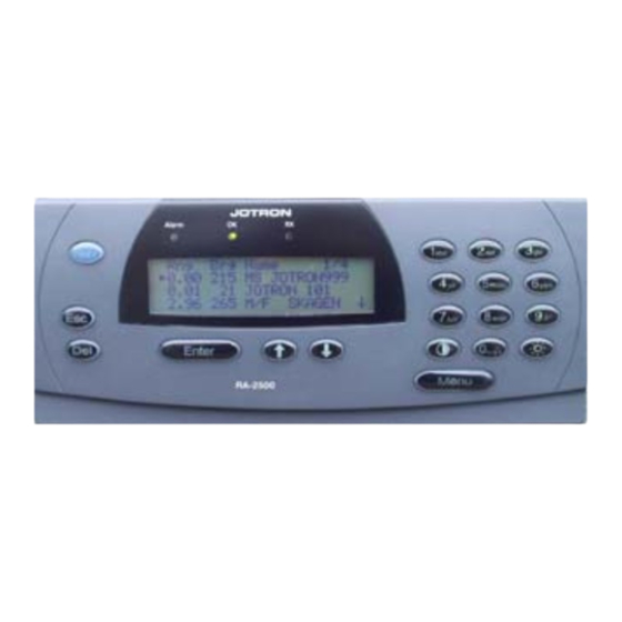
Page 27: Operation
OPERATION Figure 5.0, Front view RA-2500 Description of keys Shortcut to insert navigational data Menu Show main menu Enter Accept current setting. Takes you one menu level forward. Enter sub-menu Escape from current menu without saving. Takes you one menu level back. -
Page 28: Menus
Menus 5.2.1 Menu Flowchart Main Menu Rng Brg Name: 1 Current Sensors 2 Internal GPS 1384 124 NIKITA 3 Diagnostic 1754 124 COLOR FESTIV Menu 4 Config 99.1 098 PETER VESSEL Enter key 1 to 4 Enter NIKITA 1/14 Menu: Current Senso 1/5 MMSI: 444 LAT: N 5903.21 Call:... -
Page 29: Connecting Power
After a while the alarm status will be indicated. Press [Del] key to reset the alarm settings. If the RA-2500 has been previous configured, and the configuration is OK, there is no need to go further in this chapter. Otherwise continue with chapter 9.2.1. - Page 30 Menu: I/O Ports 1 Speed 2 Own IP Address 3 VTS IP Address Select “Own IP address” then [Enter] key Now the IP address of the RA-2500 can be entered. Menu: Own IP Addr 1 IP = 0.0.0.0 2 Port = 5000 Enter an unique IP address on the network you are connected.
-
Page 31: Normal Use
5.3.1.2 Selection of IP address Be shure that Own IP and VTS IP is within the same subnet. The configuration of Unicast, Multicast or Broadcast is dependent of the map system and the date network available. See this table for address limitations within the different groups and classes. Class Own IP VTS IP Unicast... -
Page 32: Current Sensors / Dynamic Data Menu
NIKITA 3/14 MMSI: 444 Call: ETA: ----:0000 Dest: VIKSFJORD Type:0 Lat: N58d52.58 Lon: E010d45.51 SOG: 10.0 KT COG: 3.2 Head: 45 Length: --- Beam:--- Draught: Nav.Stat Select specific information by pressing [arrow down] key and [Enter] key ETA: 30 /09 23:59 DD/MM HH:MM <... -
Page 33: Internal Gps Menu
Pos. Source: Internal HH:MM:SS DD/MM/YYYY This menu shows the data from the selected sensors onboard that the RA-2500 is receiving. Press [Esc] key twice to return to “Main Menu”. 5.4.3 Internal GPS Menu From the “Main Menu” select “Internal GPS” by pressing numeric key [4] or [arrow down] key and [Enter] key. - Page 34 This menu gives access to different submenus for readout of parameters. The only submenu who can give access to changes is the “Service” menu which is password protected. Select “BITE” menu by pressing [Enter] key or numeric key [1]. Menu: BIIT Temperature: Rssi AIS0….: Rssi AIS1.…:...
-
Page 35: Config Menu
Select “SW Version” menu by pressing numeric key [5] or [arrow down] key and press [Enter ] key. Menu: SW-Version 00.00.06 ECRA 01.00.03 MMI RA_01.00.00 LINK : 02.00.09 02.00.08 This menu shows the different software versions installed in the receiver. To get the Compilation date for each software version, select the software by [arrow up/down] keys and press [Enter] key. - Page 36 5.4.5.1 Receiver channels Select “Recv. Channels.” menu by pressing numeric key [1] or [arrow up/down] keys and press [Enter ] key. Menu: Recv. Channel 1/2 1 Ch.A: 2087 Ch.B 2088 From this menu it is possible to set the frequencies of the two receiving channels Ch.
- Page 37 Source: Surveyed ↑=Inte The Surveyed source is a static precise position to be entered manually for a RA-2500. Menu: Pos. Source Source: Surveyed Lat: 9100.000 Dir.: South Lon.: 18100.0000 Dir.: West Pos.Acc: Low Press [Esc] key to go back to “Config” menu.
- Page 38 P1 (Sensor1) 4800 ↑=4800 ↓=3840 Select speed using [arrow up/down] keys and press [ Enter] key Repeat the prosedure for all ports. Press [Esc] key to return Save Changes ? ↑= No ↓= Yes Confirm changes by [arrow up/down] keys and press [ Enter] key 5.4.5.4 Buzzer From “Config”...
-
Page 39: Description Of Sentence Format
Description of sentence format The following provides a summary explanation of the approved sentence structure: $aaccc, c---c*hh<CR><LF> ASCII Description "$" Start of sentence: starting delimiter aaccc Address field: alphanumeric characters identifying type of talker, and sentence formatter. The first two characters identify the talker. -
Page 40: Input
Input 5.6.1 Definitions BCFQ = Query BCF message from RA-2500 When the RA-2500 receives a Query, it responds with a BCF message. BCF = Configure Rx channels, Position source and Talker ID at RA-2500 5.6.2 Receiving actions VDL Input Resulting PI Output... -
Page 41: Format Bcf
5.6.3 Format BCF: Configure RA-2500 parameters. See paragraph 10.2.1 section 2. $--BCF, xxxxxxxxx,x, llll.ll, a, yyyyy.yy, a, x, xxxx, xxxx, xxxx,xxxx,x,x,x,x,cc*hh<CR><LF> receiver Talker ID Rx channel B Rx channel A Position accuracy Longitude E/W Latitude N/S Position source Notes: 1. Identifies the source of the position. -
Page 42: Output
VDM = All received VDL messages (except addressed Binary and Safety messages) are forwarded in a VDM message to the Management System. BCF = Configure Rx channels, Position source and Talker ID at RA-2500. GGA = Forward internal GPS data if position source internal. -
Page 43: Alr - Set Alarm State
5.7.3 ALR - Set alarm state. Local alarm condition and status. This sentence is used to report an alarm condition on a device and its current state of acknowledgement. $--ALR,hhmmss.ss,xxx,A, A,c--c*hh<CR><LF> Alarm's description text Alarm's acknowledge state, A = acknowledged V = unacknowledged Alarm condition (A = threshold exceeded, V = not exceeded) Local alarm number (identifier) -
Page 44: Gll Geographic Position Latitude/Longitude
Text message reaction of the system AIS: UTC clock lost Continue operation using indirect or semaphore synchronisation AIS: external DGNSS in use Continue operation AIS: external GNSS in use Continue operation AIS: internal DGNSS in use (beacon) Continue operation AIS: internal DGNSS in use (msg 17) Continue operation AIS: internal GNSS in use Continue operation... -
Page 45: Gga Global Positioning System (Gps) Fix Data
5.7.6 GGA Global positioning system (GPS) fix data Time, position and fix-related data for a GPS receiver. $--GGA, hhmmss.ss, llll.ll, a, yyyyy.yy, a, x, xx, x.x, x.x, M, x.x, M, x.x, xxxx*hh<CR><LF> Differential reference station ID 0000-1023 (Not used) Age of diff. GPS data (Not used) Units of geoidal separation,m (Not used) Geoidal separation (Not used) -
Page 46: Equipment List
For Desktop or Roof 81540 mounting of RA-2500 AC/DC External power supply 230VAC to 24VDC 81830 Power connector For 24CDC to RA-2500 81509 Combined GPS and VHF antenna 81903 82092 1 RS232 Cable 37pin to 9pin 2.5m 81650 1 AIS Graphical Viewer v.1.2.2.or... -
Page 47: Wiring And Connections
7 WIRING AND CONNECTIONS RA-2500 Rear Connections VHF Antenna Connector This is a BNC type antenna connector to be connected directly to an external VHF antenna or antenna splitter to receive and transmit VHF frequencies. For further information see chapter 8.9. -
Page 48: Description Of Junction Box Connector
This 15 pin D-sub connector is for programming of the Receiver by Program Engineers only. Extra I/O Connector This 9 pin D-sub connector is not described. Factory use only. Description of Junction Box Connector 37 Pin D-sub Functions Input / Output RA-2500 AIS TD4-B (External Display) AIS TD4-A (External Display) Isolated GND... -
Page 49: Description Of 24Vdc Connection To Receiver
Description of 24VDC connection to receiver 24VDC Connector for cable, front side 0VDC + 24VDC Description of LAN connector Contains Ethernet 10Mbit Twisted pair interface and RS232 serial port with Tx and Rx. Service connector, 9 pins Dsub: Name Function In/Out Ether_Tx+ Ethernet Transceive Data+... -
Page 50: Alarm Messages
8 ALARM MESSAGES Receiver malfunction If the error messages “Rx1”or “Rx2” appears on the LCD Display, this indicate that the test of the TDMA receivers 1 or 2 has failed. The alarm messages are as follows: Alarm ID or text identifier Alarm description text ID 003 AIS RX channel 1 malfunction... -
Page 51: List Of Vhf Channels
LIST OF VHF CHANNELS Channel Channel Channel Channel Frequency Frequency Frequency Frequency 156.3000 1021 157.0500 1279 156.9775 2219 161.5625 156.4000 1022 157.1000 1280 157.0375 2220 161.6125 156.4500 1023 157.1500 1281 157.0875 2221 161.6625 156.5000 1024 157.2000 1282 157.1375 2222 161.7125 156.5500 1025 157.2500... -
Page 52: Outline Drawings
10 OUTLINE DRAWINGS 10.1 TR-2500 AIS Transponder 82693_Op&Ins MAN_TR2500_D 10-1... -
Page 53: Procom Cxl 2-1/L
10.2 Procom CXL 2-1/l Maritime VHF Antenna with FLG Bracket 82694_Op&Ins MAN_RA2500_D 10-2... -
Page 54: Procom Gps 4 Antenna
10.3 Procom GPS 4 Antenna 82694_Op&Ins MAN_RA2500_D 10-3... -
Page 55: Bnc Connector
10.4 BNC connector 95299, Suhner 24BNC-50-2-13/133NE 10.5 FME Connector Female 80588, Holund 40100 82694_Op&Ins MAN_RA2500_D 10-4... -
Page 56: Bnc Connector Male
10.6 BNC Connector Male 80577, Suhner 11BNC-50-2 / 133NE 10.7 TNC Connector Male 80578 Suhner 11TNC-3-6 / 133NE 82694_Op&Ins MAN_RA2500_D 10-5... -
Page 57: N Connector Male
10.8 N Connector Male 80581, Suhner 11N-50-7-5 / 133NE 10.9 24VDC Power Connector 81509, AMP C091AT3261001 82694_Op&Ins MAN_RA2500_D 10-6... -
Page 58: Registration Form
Place Date Signature Please fill in with capital letters This form must be returned to Jotron AS, Fax.: + 47 33 12 67 80 (attention service department) in order to have a valid 24 months product warranty. 82693_Op&Ins MAN_TR2500_D 11-1... - Page 59 82694_Op&Ins MAN_RA2500_D 11-2...
Need help?
Do you have a question about the RA-2500 and is the answer not in the manual?
Questions and answers