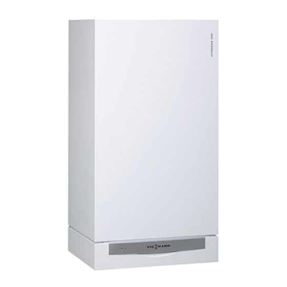
Viessmann Vitodens 200-W 19 WB2B Series Installation Instructions Manual

Viessmann Vitodens 200-W 19 WB2B Series Installation Instructions Manual

Wall-mounted, gas-fired condensing boiler
Table of Contents

Advertisement

Installation Instructions

for use by heating contractor
Vitodens 200-W, WB2B Series
Models 19, 26, 35
Wall-mounted, gas-fired condensing boiler
For operation with natural gas and liquid propane gas
Heating input
31 to 125 MBH
9 to 37 kW
VITODENS 200-W
5369 297 v1.6 12/2011
IMPORTANT
Read and save these instructions
for future reference.
 This trademark is registered with the U.S. Patent and Trademark Office.

Advertisement

Table of Contents
loading
Need help?

Need help?

Do you have a question about the Vitodens 200-W 19 WB2B Series and is the answer not in the manual?

Questions and answers

Summary of Contents for Viessmann Vitodens 200-W 19 WB2B Series

  • Page 1: Installation Instructions

    Installation Instructions  for use by heating contractor Vitodens 200-W, WB2B Series Models 19, 26, 35 Wall-mounted, gas-fired condensing boiler For operation with natural gas and liquid propane gas Heating input 31 to 125 MBH 9 to 37 kW VITODENS 200-W ...
  • Page 2 Safety, Installation and Warranty Requirements Safety, Installation and Warranty Requirements Please ensure that these instructions are read and understood before commencing installation. Failure to comply with the instructions listed below and details printed in this manual can cause product/property damage, severe personal injury, and/or loss of life.
  • Page 3: Table Of Contents

    Table of Contents Page General Information Important Regulatory and Installation Requirements ......About these Installation Instructions .
  • Page 4 Table of Contents Control Connections Electrical Connections ..................Overview of electrical connections and plug-in connectors .
  • Page 5: General Information

    - Start-up/Service Instructions Viessmann for additional copies. - Operating Instructions and User’s Information Manual This product comes with several - Instructions of other Viessmann safety instruction labels attached. products utilized and installed Do not remove! - Installation codes mentioned Contact Viessmann immediately if in this manual replacement labels are required.
  • Page 6 General Information Important Regulatory and Installation Requirements (continued) For installations on the Commonwealth of Massachusetts, the following modifications to NFPA-54 chapter 10 apply: Excerpt from 248 CMR 5-08: 2(a) For all side-wall horizontally vented gas fueled equipment installed in every dwelling, building or structure used in whole or in part for residential purposes, including those owned or operated by the Commonwealth and where the side-wall exhaust vent termination is less than (7) feet above finished grade in the area of the venting, including but not limited to decks and porches, the following requirements shall be satisfied:...
  • Page 7: About These Installation Instructions

    General Information About these Installation Instructions Take note of all symbols and notations intended to draw attention to potential hazards or important product information. These include ”WARNING”, ”CAUTION”, and ”IMPORTANT”. See below. Warnings draw your attention to the WARNING presence of potential hazards or important product information.
  • Page 8: Applicability

    General Information General Information Applicability CAUTION The boiler serial number must be provided when ordering replacement Stainless steel Inox-Radial parts. Some replacement parts are heat exchanger not reverse compatible with previous versions of the Vitodens 200-W WB2B boiler. 12-digit ASME/NB serial number (located on metallic plate riveted to the heat exchanger) IMPORTANT...
  • Page 9: Mechanical Room

    General Information Mechanical Room During the early stages of designing a new home, we recommend that proper consideration be given to constructing a separate mechanical room dedicated to the gas- or oil-fired heating equipment and domestic hot water storage tank(s). The boiler must be located in a heated indoor area, near a floor drain, and as close as possible to a wall.
  • Page 10: Set-Up

    (spraying, splashing, etc.) during boiler operation and service. Minimum Clearances Recommended minimum service clearances Side 12”/305 mm For typical Vitodens installations, Viessmann recommends installing the boiler with the clearances shown in the illustration on the left. Front 12”/305 mm Back 0”/mm...
  • Page 11: Boiler Connections

    Boiler Connections Preparing the Connections Connections overview Use an approved pipe sealant or teflon tape when connecting the following installation fittings. This section constitutes an overview only! Refer to subsequent sections for detailed information on individual piping connections. Legend Boiler Return ¾“ (NPT) Boiler Supply ¾“...
  • Page 12 Boiler Connections Preparing the Connections (continued) Connections overview (continued) Use an approved pipe sealant or teflon tape when connecting the following installation fittings. This section constitutes an overview only! Refer to subsequent sections for detailed information on individual piping connections. When preparing gas, water and electrical connections in 17¾”...
  • Page 13: Wall Mounting

    Boiler Connections Wall Mounting Installing the wall mounting bracket The Vitodens 200-W WB2B can be wall-mounted on H a brick/concrete wall H wood studs H metal studs ”/10 mm Following are the installation instructions for the mounting bracket on each material. Skip to the installation instructions applicable to your installation requirements.
  • Page 14 Boiler Connections Wall Mounting (continued) Installing the wall mounting bracket (continued) Installation of mounting bracket on wood and metal studs a = 16”/407 mm To mount the Vitodens 200-W WB2B boiler on wood or metal studs, install mounting bracket on wall as shown in Fig.
  • Page 15: Mounting The Boiler

    Boiler Connections Wall Mounting (continued) Mounting the boiler 1. To open hinged cover, lift cover A and pivot control unit flap B down. All boiler controls are located behind the control unit flap. 2. Loosen the screws at the bottom of the boiler;...
  • Page 16: Connections

    Boiler Connections Connections Connecting the power supply The Vitodens 200-W boiler is shipped Refer to the Installation Instructions See Power/Pump with a Power/Pump module, which shipped with the module or those Module Installation requires a 120 VAC power supply contained in this manual for wiring Instructions from a wall receptacle.
  • Page 17 Boiler Connections Connections (continued) Gas connection and piping 1. Refer to current CAN/CSA B149.1 and .2 or National Fuel Gas Code ANSI Z223.1/NFPA 54, as well as local codes for gas piping requirements and sizing. Pipe size to the boiler must be determined based –...
  • Page 18: Gas Connection And Piping

    Boiler Connections Connections (continued) Gas piping pressure test When performing the gas piping pressure test, ensure the following requirements are met. 1. Isolate the boiler from the gas supply WARNING piping system using the individual manual shutoff valve during pressure Never check for gas leaks with an tests equal to or less than ½...
  • Page 19: Heating Water Connections

    4 bar / 60 psig ....IMPORTANT Damage resulting from pressure exceeding those values stated is not covered by Viessmann warranty. Fig. 14 Legend Air Vent (inside boiler) Boiler Drain...
  • Page 20: Dhw Storage Tank Information

    Boiler Connections Connections (continued) DHW storage tank information The DHW water tank sensor is required when using a stand-alone DHW storage tank with the Vitodens 200-W WB2B heating boiler. It comprises the sensor only required for the connection of a stand-alone tank. All other required piping connections are field supplied.
  • Page 21 Refer to the Vitocell 300 Installation Instructions shipped with the DHW storage tank for details. IMPORTANT Follow the Installation Instructions supplied with the Viessmann DHW storage tank when mounting and securing DHW tank temperature sensor WARNING IF A DHW STORAGE TANK OTHER...
  • Page 22: Accessing The Control Unit Cables

    Boiler Connections Connections (continued) Accessing the control unit cables 1. To open hinged cover, lift cover and pivot control unit flap down. 2. Release the hinged hooks located on both sides of the control unit. 3. Fold down the control unit. 4.
  • Page 23: Connecting Dhw Sensor

    See table 2 or the Viessmann Price List for order information. 1.Pull out the existing coding card, cut and remove it from the cable tie.
  • Page 24: Condensate Connection

    Boiler Connections Connections (continued) Condensate connection The Vitodens 200-W WB2B boiler comes with a built-in condensate trap. An external trap is not required when connecting the field drain to flexible discharge tubing. Discharge tubing (field supplied) must be of 1” diameter. Use CPVC, PVC or other material approved by codes listed below.
  • Page 25: Safety Connections And Pressure Testing

    Boiler Connections Safety Connections and Pressure Testing Installing boiler safety devices 1. Remove loosely pre-assembled Minimum connection diameters: combination pressure relief valve and Pressure relief valve ¾“ ......drain valve assembly.
  • Page 26: Performing Boiler Pressure Test

    Boiler Connections Safety Connections and Pressure Testing (continued) Performing a boiler pressure test The boiler must be leak tested before Max. operating pressure being placed in operation. Before boiler 3 bar / 45 psig ..........is connected to piping or electrical Testing pressure power supply, it must be...
  • Page 27: Installation Examples

    If a DHW storage tank other than a The examples on the following pages DHW supply and return piping between Viessmann Vitocell 100 or 300 tank depict possible piping layouts of the boiler DHW connections and the is used, the installer must verify...
  • Page 28: Waterside Flow (Primary Circuit)

    (as stated above), falls below the minimum flow rate or if system flow rate is unknown, Viessmann strongly recommends the installation of a low-loss header. Table 3. Typical System Flow Rates Model WB2B ∆...
  • Page 29: System Layout 1

    Boiler Connections Installation Examples (continued) System layout 1 Vitodens 200-W, WB2B with a direct-connected heating circuit Fig. 23 Legend Installation of ... H radiator heating circuit (high-temp. circuit) IMPORTANT AV Air vent (models WB2B 19, 26, 35) H DHW production PRV Pressure relief valve ...
  • Page 30: System Layout 2

    28, or if the DHW recirculation pump sK* system flow rates are unknown. Power/Pump Module The low-loss header is available as M Low-loss header accessory part. N Optional purge tee (field supplied) O Viessmann temperature sensor for low-loss header...
  • Page 31: System Layout 3

    (see IMPORTANT note to the right) pump may cause short-cycling and/or accessory part. Plate heat exchanger for system improper operation of the boiler. Viessmann separation STRONGLY recommends using a low-loss See following pages for installation Accessory kit for heating circuit with header and a boiler pump in this system examples with a low-loss header.
  • Page 32: System Layout 4

    Boiler Connections Installation Examples (continued) System layout 4 Vitodens 200-W, WB2B with... – DHW storage tank – one direct-connected heating circuit – one heating circuit with a mixing valve Fig. 26 Legend * See pages 52 and 56. See following pages for additional AV Air vent (WB2B models 19, 26, 35) installation examples with a low-loss Installation of different heating circuits...
  • Page 33: System Layout 5

    – DHW storage tank – one heating circuit with mixing valve – one heating circuit without mixing valve and with low-loss header Fig. 27 S Viessmann temperature sensor for Legend IMPORTANT low-loss header AV Air vent (WB2B models 19, 26, 35)
  • Page 34: System Layout 6

    – two heating circuits with a mixing valve and low-loss header Fig. 28 T Flow check valve multi-boiler control. Contact your local Legend Viessmann Technical Sales Representative AV Air vent (WB2B models 19, 26, 35) for details. PRV Pressure relief valve * See pages 52 and 56.
  • Page 35: System Layout 7

    Boiler Connections Installation Examples (continued) System layout 7 Vitodens 200-W, WB2B with... – direct-connected heating circuit – one heating circuit with system separation Fig. 29 Legend * See pages 52 and 56. IMPORTANT AV Air vent (WB2B models 19, 26, 35) PRV Pressure relief valve Installation of different heating circuits...
  • Page 36: System Layout 8

    Vitodens 200-W, WB2B with... – DHW storage tank – low-loss header – multiple heating circuits with mixing valves Fig. 30 When designing a system as illustrated above, please contact your local Viessmann Sales Representative for assistance. DHW storage tank Legend IMPORTANT Expansion tank...
  • Page 37: Vitodens 200-W, Wb2B (Alternate Dhw Connection)

    Boiler Connections Installation Examples (continued) Vitodens 200-W, WB2B (alternate DHW connection) The following piping diagram reflects an alternative connection for the DHW tank only and applies to system layouts 2, 5, 6 and 8. The boiler control pump logic function must be programmed in the Start-up/Service Instructions. . Alternative location of the expansion tank...
  • Page 38: Boiler In Heating/Cooling Application

    Expansion tank Close valve v2 and open valve v1. Water chiller Boiler circuit pump (field supplied) IMPORTANT Viessmann strongly suggests that the valves pictured above be labelled “v1” and “v2”. IMPORTANT In the above system, the circulating pump must be operated from a separate on/off switch, not from the pump aquastat on the boiler control.
  • Page 39: Boiler With Low Water Cut-Off (Remote-Mounted, Field Supplied)

    Boiler Connections Boiler Connections Installation Examples (continued) Boiler with low water cut-off (remote-mounted, field supplied) A low water cut-off may be required by Hi-Vent Hi-Vent local codes. If boiler is installed above radiation level, a low water cut-off device of approved type (field supplied) must be installed in all instances at the highest point of the piping system.
  • Page 40: Electrical Connections

    Control Connections Electrical Connections Overview of electrical connections and plug-in connectors Power supply connection of accessories The power supply connection of accessories can be made directly at the control. The connection is activated and deactivated with the system on/off switch. The Vitotronic 200-H, HK1M mixing valve control, the mixing valve accessory kit and the Solartrol control require a separate 120 VAC power supply from the wall receptacle.
  • Page 41 Control Connections Electrical Connections (continued) Connecting the Power/Pump module (continued) 1. Remove the cover of the power pump module. Using the four screws supplied, mount the module base on the wall next to the Vitodens boiler. 2. Secure the connecting cables to the wall using the supplied conduit holding clips.
  • Page 42: Power/Pump Module Electrical Connectors

    Control Connections Electrical Connections (continued) Power/Pump module electrical connectors Power/Pump Module 1 2 3 1 2 3 1 2 3 120/230 Transformer 1 2 3 1 2 3 1 2 3 L1 G N L G N Fig. 36 Legend - Power supply - System pump - DHW pump...
  • Page 43 Control Connections Electrical Connections (continued) Boiler control board GC 130 electrical connections Boiler Control Board GC 130 Fig. 37 Legend - Power supply sÖ - Boiler pump - LON/cascade communication module - Terminal block (low-loss header sensor, outdoor sensor and KM BUS connection) - KM-BUS connection to the Power/Pump module...
  • Page 44: Connection Between The Power/Pump Module And Boiler

    Control Connections Electrical Connections (continued) Connection between the Power/Pump module and boiler Power/Pump module MAIN POWER SUPPLY 120V, 60HZ, 12A MAIN DISCONNECT SWITCH 120/230 Transformer 1 2 3 1 2 3 L1G N L G N 120VAC WALL RECEPTACLE 1. Remove and discard the green factory test lead plug 230 VAC equipped) from the boiler control...
  • Page 45: Accessories Electrical Connections

    Control Connections Electrical Connections (continued) Accessories electrical connections See the following pages for connection to the individual accessories. Power/Pump module MAIN POWER SUPPLY 120V, 60HZ, 12A MAIN DISCONNECT SWITCH 120/230 Transformer 1 2 3 1 2 3 1 2 3 120VAC L1 G N L G N...
  • Page 46: Accessing The X3 Plug

    Control Connections Electrical Connections (continued) Accessing the X3 plug 1. Remove the control unit cover (see page 23). 2. Remove the X3 plug from the control board. Attach sensors and/or KM-BUS and/or accessories and reinsert the X3 plug. Refer to the following sensor information.
  • Page 47: Connecting The Outdoor Temperature Sensor

    Control Connections Electrical Connections (continued) Connecting the outdoor temperature sensor 1. Remove cover of outdoor temperature sensor. 2. Mount wall-mount base (cable entry must point downward). IMPORTANT The outdoor temperature sensor should be mounted 6.6 to 8.2 ft./ 2 to 2.5 m above ground level on the north or northwest wall of the building.
  • Page 48: External Switching Of Heating Program/External Heat Demand External Blocking

    Control Connections Electrical Connections (continued) External switching of heating program/External heat demand / External blocking aVD - External blocking terminals 2-3 External demand terminals 1-2 External heating program changeover terminals 1-2 The allocation of the function “external heating program changeover” is set via coding Power/Pump module address ‘91’...
  • Page 49: Connecting The Lon Communication Module

    Control Connections Electrical Connections (continued) Connecting the LON communication module Installing the LON module to the Vitotronic 200-H, HK1M mixing valve controller 1. Remove the Vitotronic 200-H, HK1M front cover. 2. Insert the LON module into the Vitotronic 200-H, HK1M control board.
  • Page 50 Control Connections Electrical Connections (continued) Connecting the LON communication module (continued) Boiler Control Board GC130 Fig. 48 See the Vitotronic 200-H, HK1M Installation Instructions.
  • Page 51: Accessory Kit Connections For Heating Circuit With Mixing Valve Part No. 7133392 (Old Version)

    Control Connections Electrical Connections (continued) Accessory kit connections for heating circuit with mixing valve part no. 7133392 (old version) Mixing Valve Controller Dip Switch Setting Boiler Control Board GC130 Fig. 49 See the Mixing Valve Controller Kit for one heating circuit with mixing valve Installation Instructions.
  • Page 52: Accessory Kit Connections For Heating Circuit With Mixing Valve Part No. 7837524 (New Version)

    Control Connections Electrical Connections (continued) Accessory kit connections for heating circuit with mixing valve part no. 7837524 (new version) The mixing valve controller kit can only be used with wall-mounted gas-fired hot water heating boilers and a weather-responsive control; it can be used as an alternative for a Vitotronic 050/Dekamatik-HK1 control.
  • Page 53: Wiring Diagram For The Boiler / Power/Pump Module

    Control Connections Electrical Connections (continued) Wiring diagram for the boiler / Power/Pump module X9.3 X9.4 GC130 BOILER/BURNER CONTROL MODULE KM--BUS Accessories Conduit WH GN b -- MAIN POWER SUPPLY 5 - - 120V, 60HZ, 12A N G L MAIN 2 - - DISCONNECT SWITCH Power Pump Module...
  • Page 54: Closing The Control Unit And Inserting The Programming Unit

    2. Tighten screws at the bottom. IMPORTANT Read and follow, where applicable, the safety instructions of all labels and stickers attached to boiler surfaces. Do not remove any of these instructions. Contact Viessmann if any replacement labels are required Fig. 52...
  • Page 55: Technical Data

    Additional Information Technical Data Table 4 Boiler Model Model No. WB2B Natural gas / Liquid propane gas 31-67 31-93 31-125 CSA input 9-20 9-27 9-37 28-61 28-85 28-114 CSA output/DOE 8-18 8-25 8-33 heating capacity Net I=B=R rating 10.23 10.23 10.23 Heat exchanger surface area 0.95...
  • Page 56: Additional Information

    Do not attempt to common-vent Vitodens 200-W WB2B with any other appliance. For details refer to the Installation Instructions for the Vitodens 200-W, WB2B Venting System. " For information regarding other Viessmann System Technology componentry, please reference documentation of respective product.
  • Page 57: Wiring Diagram

    Additional Information Wiring Diagram Complete system wiring diagram 99 C 210 F X1 X2 INTERNAL CONNECTIONS X8.1 X8.10 X8.11 X9.1 GC130 BURNER IGNITION MODULE X9.3 X9.4 WARNING! DISCONNECT POWER BEFORE SERVICING BOILER. CAUTION! LABEL ALL WIRES PRIOR TO DISCONNECTION WHEN SERVICING CONTROLS. WIRING ERRORS CAN CAUSE IMPROPER AND 1 2 3 4 5 6 7 DANGEROUS OPERATION.
  • Page 58 Additional Information Wiring Diagram (continued) Complete system wiring diagram (continued) Legend Outside Temperature Sensor Fixed High Limit A1 Main PCB (GC130 Ignition Module) Flow Temperature Sensor/Low Loss Header Fault Alarm Output A2 Internal Power Supply Unit Ignition Transformer Boiler Water Temperature Sensor A3 Optolink DHW Temperature Sensor Power Supply Accessory (Not Used)
  • Page 59: Lighting And Operating Instructions

    Additional Information Lighting and Operating Instructions FOR YOUR SAFETY READ BEFORE OPERATING W A R N I N G: If you do not follow these instructions exactly, a fire or explosion may result causing property damage, personal injury or loss of life. A.
  • Page 60: Ladder Diagram

    Additional Information Ladder Diagram Legend -X1 [40] power supply 120 VAC -X1 [20A] pump, HTG system w/o mixing valve, 120 VAC -X1 [21] pump DHW tank 120 VAC -X1 [20] pump boiler 120 VAC -X1 [50] fault alarm 120 VAC -X2 [28] pump, DHW recirculation, 120 VAC IMPORTANT...
  • Page 61 5369 297 v1.6...
  • Page 62 5369 297 v1.6...
  • Page 63 5369 297 v1.6...
  • Page 64 Viessmann Manufacturing Company (U.S.) Inc. Viessmann Manufacturing Company Inc. 45 Access Road 750 McMurray Road Warwick, Rhode Island • 02886 • USA Waterloo, Ontario • N2V 2G5 • Canada Tel. (401) 732-0667 • Fax (401) 732-0590 Tel. (519) 885-6300 • Fax (519) 885-0887 www.viessmann-us.com •...

Table of Contents