
Summary of Contents for A & T Internationale Xserve
- Page 1 Service Source Xserve (Late 2006) Xserve (Late 2006), Xserve (Early 2008) Updated: 23 December 2008 © 2006, 2007, 2008 Apple Inc. All rights reserved.
- Page 2 Every effort has been made to ensure that the information in this document is accurate. Apple is not responsible for printing or clerical errors. Apple 1 Infinite Loop Cupertino, CA 95014-2084 + 1 408 996 1010 www.apple.com Apple, the Apple logo, and Xserve are trademarks of Apple Inc., registered in the U.S. and other countries.
-
Page 3: Table Of Contents
Front Panel Board Cable 45 Backplane-to-Logic Board I/O Cable 47 Optical Drive Cable 50 Locking Mechanism Rod 53 Front Bezel Assembly for Xserve (Late 2006) 56 Front Bezel Assembly for Xserve (Early 2008) 59 Front Bezel Brackets for Xserve (Early 2008) 62... - Page 4 Power Distribution Board 87 Processor Heat Sink 89 Processor 99 Video Mezzanine Card 105 Logic Board 107 Removal Procedure 109 Packing the Used Logic Board: Xserve (Early 2008) Only 113 Replacement Procedure 115 Rear ID Button 117 ID Tab 119 Enclosure 122 Troubleshooting General Information 125 What’s New 125...
- Page 5 FireWire Devices 147 Network Problems 148 Views Internal Views 150 Exploded View 1: Xserve (Late 2006) 150 Exploded View 2: Xserve (Late 2006) 151 Exploded View 1: Xserve (Early 2008) 152 Exploded View 2: Xserve (Early 2008) 153 External Views 154...
-
Page 6: Take Apart
Service Source Take Apart Xserve (Late 2006) © 2006, 2007, 2008 Apple Inc. All rights reserved. -
Page 7: Manual Updates
Manual Updates 8 January 2008 Introduced the Xserve (Early 2008) server with the following service manual updates: Take Apart • Added new “Manual Updates” section • General Information: Added reference to new model, added front panel image, and revised the sections “What’s New” and “A Note on the Images”... -
Page 8: General Information
(Early 2008) model is the port next to the system identifier button on the front bezel. On the Xserve (Late 2006) model, it is a FireWire 400 port; whereas on the Xserve (Early 2008) model, it is a USB port, as shown below. -
Page 9: Mounting In A Rack
To distinguish the Xserve (Late 2006 or Early 2008) models from the previous Xserve G5 model, check the rear panel. Xserve (Late 2006) and Xserve (Early 2008) have two power supply bays on the right side of the rear panel. Previous Xserve G5 models have a single, built-in power supply. - Page 10 Note: A duplicate identifier light/button is on the Xserve’s back panel. A Note on the Images The photos and drawings in this manual were based on a pre-production unit. Your Xserve may look slightly different from the one shown in the images. Likewise, the instructions apply to more than one Xserve model.
-
Page 11: Apple Drive Module
† PATA connector is physically different from SAS connector so this ADM will not fit completely into slot. †† Will fit completely into slot but ADM will not work or be recognized by the Xserve. Installing the SAS ADM should not damage the drive, however. -
Page 12: Preliminary Steps
Before you begin, make sure the drives are in the unlocked position. Also, make sure the drive being replaced is not in use by any application and is not being shared by the Xserve. (See the Mac OS X Server documentation for information about shared drives.) To do this, you may need to first unmount the drive by using the command-line tools or by dragging the disk icon to the Trash. - Page 13 Make sure the drive being replaced is not in use by any application and is not being shared by the Xserve. (See the Mac OS X Server documentation for information about shared drives.) Unmount the drive (by using the command-line tools or by dragging the volume icon to the Trash).
- Page 14 Name the volume “Macintosh HD.” Apply the change by clicking the Partition tab. Leave the Disc Utility application open, and restore the backed up files from the image you created before removing the hard drive. Xserve (Late 2006) Take Apart — Hard Drive Module...
-
Page 15: Power Supply
You can replace or install a power supply from the back panel without removing the server from the rack. If the Xserve has two power supplies, they are hot-swappable; the Xserve will continue to operate using only one supply while the second is removed. -
Page 16: Replacement Procedure
Connect the power cord to the power supply. Note: If the Xserve is already running on a second power supply, the status light on the new supply turns green to indicate normal operation as it starts sharing the load. If the Xserve is not turned on, the supply status light blinks green when the power cord is plugged in to an outlet with power. -
Page 17: Power Supply Blank
The power supply blank may be removed while the server is still in the rack. Tools No tools are required for this procedure. Preliminary Steps There are no preliminary steps for this procedure. Part Location Xserve (Late 2006) Take Apart — Power Supply... - Page 18 Procedure Pull out the handle to swing open the power supply blank. Notice the hook that catches on the inside bottom of the power supply bay. Xserve (Late 2006) Take Apart — Power Supply...
- Page 19 Replacement Note: Align the hook on the power supply blank with the catch inside the power supply bay. Close the power supply blank, and press the handle over the bay wall to lock it in place. Xserve (Late 2006) Take Apart — Power Supply...
-
Page 20: Opening The Top Cover
Opening the Top Cover The top cover on this Xserve model does not remain installed in the rack as it did in previous Xserve G5 models. The entire Xserve enclosure, including its top cover, must be removed from the rack as a unit before the top cover can be removed to gain access to any internal components. -
Page 21: Shutting Down
Unlocking the Server If the Xserve is in the locked position (the yellow security LED on the front panel is on), use the Allen key that came with the Xserve to unlock it. The lock secures the Xserve enclosure top cover and all three drive modules. - Page 22 When the safety latches engage, grip the Xserve where it emerges from the rack, press down on the latch tabs with your thumbs, and slide the Xserve the rest of the way out of the rack rails. Set the Xserve on a flat surface.
-
Page 23: Fb-Dimm Memory
FB-DIMM Memory The Xserve (Late 2006) has 8 memory slots. The systems come with at least 1 gigabyte (GB) of memory on two fully-buffered dual inline memory modules (FB-DIMMs). To improve performance and capacity, you can install additional DIMMs for a total of up to 32 GB of memory. The 8 memory slots are labeled DIMM 1 through DIMM 8. - Page 24 1 through 4, add a full set of four DIMMs in slots 5 through 8 instead of just a pair in slots 5 and 6. Tools No tools are required for this procedure. Preliminary Steps Before you begin, open the Xserve and place the bottom housing on a sturdy, flat surface. Xserve (Late 2006) Take Apart — FB-DIMM Memory...
- Page 25 Part Location DIMM slots (8) Procedure Push down the ejectors on the DIMM slot. Holding the DIMM by both top corners, lift it straight up out of the Xserve. Ejectors Notch Connectors Warning: When removing or installing the DIMM, handle it only by the edges. Do not touch its connectors.
-
Page 26: Pci-X And Pci-E Riser Cards
The only tool required for this procedure is a Phillips #1 screwdriver. Preliminary Steps Before you begin, open the Xserve and place the bottom housing on a sturdy, flat surface. Important: Be sure the Xserve is turned off and unplugged before you install or remove an expansion card or riser. - Page 27 If you are removing a riser card so that you can replace it with a new riser card, remove any expansion card installed in the original riser card and transfer the card to the replacement riser. Xserve (Late 2006) Take Apart — PCI-X and PCI-E Riser Cards...
-
Page 28: Pci-X And Pci-E Expansion Cards
The only tool required for this procedure is a Phillips #1 screwdriver. Preliminary Steps Before you begin, open the Xserve and place the bottom housing on a sturdy, flat surface. Important: Be sure the Xserve is turned off and unplugged before you install or remove an expansion card or riser. - Page 29 Carefully pull up on the bracket and riser, with the expansion card still attached, to disconnect the riser from the logic board. Captive screws Tilt the expansion card up so that its port clears the enclosure, and remove the card from the Xserve. Xserve (Late 2006) Take Apart — PCI-X and PCI-E Expansion Cards...
- Page 30 Replacement Procedure Seat the expansion card in the riser slot and replace the screw to secure the card in the riser. Screw PCI card PCI riser Xserve (Late 2006) Take Apart — PCI-X and PCI-E Expansion Cards...
- Page 31 • To configure an Ethernet card, open the Network pane of System Preferences. • To configure a Fibre Channel card, open Fibre Channel Utility. • To configure a SCSI card, open Disk Utility. Xserve (Late 2006) Take Apart — PCI-X and PCI-E Expansion Cards...
-
Page 32: Battery In Xserve (Late 2006)
Battery in Xserve (Late 2006) The Xserve (Late 2006) uses a CR 2032 Lithium coin cell battery to preserve settings such as the date and time when the system is not connected to power. If the date and time change unexpectedly or other system settings are lost, you might need to replace the battery. - Page 33 If you removed a riser card and/or an expansion card, replace it. Close the Xserve and return it to the rack. Important: Dispose of the old battery according to the manufacturer’s instructions and your local environmental laws. Xserve (Late 2006) Take Apart — Battery in Xserve (Late 2006)
-
Page 34: Battery In Xserve (Early 2008)
Battery in Xserve (Early 2008) The Xserve (Early 2008) uses a CR 2032 Lithium coin cell battery to preserve settings such as the date and time when the system is not connected to power. If the date and time change unexpectedly or other system settings are lost, you might need to replace the battery. - Page 35 Insert the replacement battery in the holder with the positive side (+) up and the negative side down. Important: Dispose of the old battery according to the manufacturer’s instructions and your local environmental laws. Close the Xserve and return it to the rack. Xserve (Late 2006) Take Apart — Battery in Xserve (Early 2008)
-
Page 36: Optical Drive
The only tool required for this procedure is a jeweler’s Phillips (#0) screwdriver. Preliminary Steps Before you begin, open the Xserve and place the bottom housing on a sturdy, flat surface. Part Location Xserve (Late 2006) Take Apart — Optical Drive... - Page 37 Important: When removing or replacing the optical drive, be careful not to put pressure on the top of the drive or the top of the front bezel that covers the optical drive slot. LIft the drive out of the server. Xserve (Late 2006) Take Apart — Optical Drive...
- Page 38 Remove the three mounting screws for the right bracket and transfer the bracket to the new drive, again using the same screws to secure it. Xserve (Late 2006) Take Apart — Optical Drive...
-
Page 39: Airflow Duct
The only tool required for this procedure is a Phillips #1 screwdriver Preliminary Steps Before you begin, open the Xserve and place the bottom housing on a sturdy, flat surface. Part Location Xserve (Late 2006) Take Apart — Airflow Duct... - Page 40 Loosen the five Phillips screws that fasten the airflow duct to the fan array. Pull up on either side of the airflow duct, and lift it straight up and out of the Xserve. Caution: Try not to completely remove the screws from the airflow duct. Tiny black rubber washers hold these screws captive on the underside of the airflow duct.
- Page 41 • Tighten the five Phillips screws that fasten the airflow duct to the fan array, in the order shown, to prevent the duct from warping. Do not overtighen the screws. Xserve (Late 2006) Take Apart — Airflow Duct...
-
Page 42: Fan Array
1 below. Preliminary Steps Before you begin, do the following: • Open the Xserve and place the bottom housing on a sturdy, flat surface. • Remove the airflow duct. Part Location Xserve (Late 2006) Take Apart — Fan Array... - Page 43 Loosen the two thumbscrews that secure the fan array to the enclosure. Note: The thumbscrews are captive; you cannot remove them. Lift the fan array to remove it from the Xserve. Note: You may need to move the front panel cable slightly out of the way of the fan array power connector during removal or replacement.
- Page 44 Then lift the fan array out of the computer. Replacement Note: When installing the fan array, make sure a foam strip is included, as shown below. Xserve (Late 2006) Take Apart — Fan Array...
-
Page 45: Front Panel Board Cable
No tools are required for this procedure. Preliminary Steps Before you begin, do the following: • Open the Xserve and place the bottom housing on a sturdy, flat surface. • Remove the airflow duct. • Remove the left PCI riser card and any expansion card in slot 1. - Page 46 Release the locking levers on the cable connectors and disconnect the front panel board cable from the front panel board and the logic board. Remove the cable from the Xserve. Xserve (Late 2006) Take Apart — Front Panel Board Cable...
-
Page 47: Backplane-To-Logic Board I/O Cable
No tools are required for this procedure. Preliminary Steps Before you begin, do the following: • Open the Xserve and place the bottom housing on a sturdy, flat surface. • Remove the airflow duct. Part Location Xserve (Late 2006) Take Apart — Backplane-to-Logic Board I/O Cable... - Page 48 Procedure Disconnect the backplane-to-logic board cable from the logic board. Disconnect the backplane-to-logic board cable from the drive interconnect backplane and remove the cable from the Xserve. Xserve (Late 2006) Take Apart — Backplane-to-Logic Board I/O Cable...
- Page 49 Replacement Note: Connect the cable to the logic board first. Then press the adhesive section of the cable onto the enclosure before connecting the other end of the cable to the backplane. Caution: Make sure the cable is fully seated. Xserve (Late 2006) Take Apart — Backplane-to-Logic Board I/O Cable...
-
Page 50: Optical Drive Cable
Tools No tools are required for this procedure. Preliminary Steps Before you begin, do the following: • Open the Xserve and place the bottom housing on a sturdy, flat surface. • Remove the airflow duct • Remove the fan array Part Location Xserve (Late 2006) Take Apart —... - Page 51 Disconnect the optical drive cable from the optical drive. Disconnect the optical drive cable from the logic board. Carefully pry the cable’s adhesive from the enclosure and remove the cable from the Xserve. Replacement Note: Fold the replacement optical drive cable to 90-degree angles along its creases.
- Page 52 Replacement Note: Connect the replacement optical drive cable to the logic board first. Then press the adhesive section of the cable onto the enclosure before connecting the other end of the cable to the optical drive. Xserve (Late 2006) Take Apart — Optical Drive Cable...
-
Page 53: Locking Mechanism Rod
Xserve (Late 2006) and Xserver (Early 2008). Tools No tools are required for this procedure. Preliminary Steps Before you begin, open the Xserve and place the bottom housing on a sturdy, flat surface. Part Location Xserve (Late 2006) Take Apart — Locking Mechanism Rod... - Page 54 To install the gear, slide it onto the notched end of the locking rod, aligning the narrow end of the gear with the end of the rod. Note: Make sure the rib inside the gear engages with the notch in the rod. Xserve (Late 2006) Take Apart — Locking Mechanism Rod...
- Page 55 To install the locking rod, insert the key-hole end of the rod into the port on the front bezel. Note: Make sure the small circle on the front of the rod points to the left. It should align with the “unlocked” symbol on the bezel. Xserve (Late 2006) Take Apart — Locking Mechanism Rod...
-
Page 56: Front Bezel Assembly For Xserve (Late 2006)
Front Bezel Assembly for Xserve (Late 2006) Note: Although the illustrations for this procedure are based on Xserve G5, the procedure is the same for Xserve (Late 2006). Tools The only tool required for this procedure is a Phillips screwdriver. - Page 57 Gently pull the front bezel forward and remove it from the server. Important: When removing or replacing the bezel, be careful not to put pressure on the top of the bezel over the optical drive slot. Xserve (Late 2006) Take Apart — Front Bezel Assembly for Xserve (Late 2006)
- Page 58 Replace the front bezel on the server, matching ports/projections with openings. Replace the screw that secures the top of the bezel to the server. Replace the two bezel brackets and their mounting screws. Xserve (Late 2006) Take Apart — Front Bezel Assembly for Xserve (Late 2006)
-
Page 59: Front Bezel Assembly For Xserve (Early 2008)
Tools The only tool required for this procedure is a Phillips screwdriver. Preliminary Steps Before you begin, open the Xserve and place the bottom housing on a sturdy, flat surface. Part Location Removal Procedure From behind the front bezel, locate the four screws and two brackets. Remove the four identical 4-mm long screws and the two brackets. - Page 60 To prevent damage to the buttons, be sure to align the buttons with the front panel openings as you install a replacement front bezel. Xserve (Late 2006) Take Apart — Front Bezel Assembly for Xserve (Early 2008)
- Page 61 Place the front bezel on the server, carefully matching openings with buttons and ports. Replace the bezel brackets, four 4-mm long screws, and 8-mm long center screw with star washer. Xserve (Late 2006) Take Apart — Front Bezel Assembly for Xserve (Early 2008)
-
Page 62: Front Bezel Brackets For Xserve (Early 2008)
The only tool required for this procedure is a Phillips screwdriver. Preliminary Steps Before you begin, open the Xserve and place the bottom housing on a sturdy, flat surface. Part Location Xserve (Late 2006) Take Apart — Front Bezel Brackets for Xserve (Early 2008) - Page 63 Replacement Procedure Position the right replacement bracket on the server, and install its two mounting screws. Repeat for the left replacement bracket. Xserve (Late 2006) Take Apart — Front Bezel Brackets for Xserve (Early 2008)
-
Page 64: Front Panel Buttons
Tools The only tool required for this procedure is a Phillips screwdriver. Preliminary Steps Before you begin, open the Xserve; place the bottom housing on a sturdy, flat surface; and remove the front bezel assembly. Part Location Xserve (Late 2006) Take Apart — Front Panel Buttons... - Page 65 Note: Take care in handling the buttons. The face of each button is loosely attached to the button LEDs and can easily separate. Replacement Note: Position the replacement buttons in the front bezel as illustrated. Xserve (Late 2006) Take Apart — Front Panel Buttons...
-
Page 66: Light Pipe For Xserve (Late 2006)
Light Pipe for Xserve (Late 2006) Note: Although the illustrations for this procedure are based on Xserve G5, the procedure is the same for Xserve (Late 2006). Tools The only tool required for this procedure is a Phillips screwdriver. Preliminary Steps Before you begin, open the Xserve;... - Page 67 Remove the light pipe assembly from the server. Replacement Procedure Position the light pipes in the replacement light pipe assembly into the double row of light pipe holes in the front bezel. Xserve (Late 2006) Take Apart — Light Pipe for Xserve (Late 2006)
- Page 68 Replace the front bezel on the server, matching ports/projections with openings. Replace the screw that secures the top of the bezel to the server. Replace the two bezel brackets and their mounting screws. Xserve (Late 2006) Take Apart — Light Pipe for Xserve (Late 2006)
-
Page 69: Light Pipe For Xserve (Early 2008)
Tools The only tool required for this procedure is a Phillips screwdriver. Preliminary Steps Before you begin, open the Xserve; place the bottom housing on a sturdy, flat surface; and remove the front bezel assembly. Part Location Xserve (Late 2006) Take Apart — Light Pipe for Xserve (Early 2008) - Page 70 Replace the front bezel on the server, matching ports/projections with openings. Replace the screw that secures the top of the bezel to the server. Replace the two bezel brackets and their mounting screws. Xserve (Late 2006) Take Apart — Light Pipe for Xserve (Early 2008)
-
Page 71: Front Panel Board
The only tool required for this procedure is a Phillips #1 screwdriver. Preliminary Steps Before you begin, do the following: • Open the Xserve and place the bottom housing on a sturdy, flat surface. • Remove the locking mechanism rod. Part Location... - Page 72 Release the two locking levers on the front panel board cable connector and disconnect the cable from the front panel board. Remove the two Phillips screws that mount the front panel board to the chassis. Xserve (Late 2006) Take Apart — Front Panel Board...
- Page 73 Slide the board back slightly and release the two clips on either side of it. Tilt the board up and remove it from the Xserve. Important: When replacing the front panel board, make sure the board slides under the black plastic cover of the light pipe.
-
Page 74: Drive Interconnect Backplane
No tools are required for this procedure. You may, however, find a Phillips screwdriver useful in releasing the thumbscrew. Preliminary Steps Before you begin, do the following: • Open the Xserve and place the bottom housing on a sturdy, flat surface. • Remove all Apple drive modules. • Remove the airflow duct. - Page 75 Disconnect the backplane-to-logic board I/O cable from the backplane. Replacement Note: Make sure the cable is fully seated when reconnected. Loosen the captive thumbscrew that secures the backplane to the enclosure. Xserve (Late 2006) Take Apart — Drive Interconnect Backplane...
- Page 76 Be careful not to let any backplane components come into contact with the standoffs or the enclosure as you remove the backplane. Xserve (Late 2006) Take Apart — Drive Interconnect Backplane...
- Page 77 Then rotate the backplane downward and over the four mushroom-shaped standoffs. Finally, slide the backplane in the direction of the arrow shown to fully seat the backplane in the enclosure. Xserve (Late 2006) Take Apart — Drive Interconnect Backplane...
-
Page 78: Xserve Raid Card
No tools are required for this procedure. You may, however, find a Phillips screwdriver useful in releasing the thumbscrew. Preliminary Steps Before you begin, do the following: • Open the Xserve and place the bottom housing on a sturdy, flat surface. • Remove all Apple drive modules. • Remove both power supplies. - Page 79 Move the front panel board cable out of the way. Disconnect the backplane-to-logic board I/O cable from the Xserve RAID Card. Disconnect the Xserve RAID Card battery cable from the Xserve RAID Card. Xserve (Late 2006) Take Apart — Xserve RAID Card...
- Page 80 Release the thumbscrew that secures the Xserve RAID Card to the enclosure. Note: The thumbscrew is captive; you cannot remove it. Shift the Xserve RAID Card toward the enclosure side, in the direction of the arrow shown, until it clears the four mushroom-shaped standoffs that hold the card in place.
- Page 81 (as shown), and carefully align the front edge of the card with the four alignment slots in the enclosure. Be careful not to let any Xserve RAID Card components come into contact with the standoffs or the enclosure as you install the card.
-
Page 82: Power Distribution Board Cable
The only tool required for this procedure is a nylon probe tool or similar plastic pry tool. Preliminary Steps Before you begin, open the Xserve and place the bottom housing on a sturdy, flat surface. Part Location Xserve (Late 2006) Take Apart — Power Distribution Board Cable... - Page 83 Disconnect the power distribution board cable from its connector on the drive interconnect backplane. Disconnect the power distribution board cable from the power distribution board and remove the cable from the Xserve. Xserve (Late 2006) Take Apart — Power Distribution Board Cable...
-
Page 84: Xserve Raid Card Battery
No tools are required for this procedure. Preliminary Steps Before you begin, do the following: • Open the Xserve and place the bottom housing on a sturdy, flat surface. • Remove all Apple drive modules. • Remove both power supplies. - Page 85 Procedure Lift the Xserve RAID Card battery straight up off its three mounting posts. Note: Adhesive on the underside of the battery holds it in place on the enclosure floor. Remove the battery from the enclosure. Replacement Note: Before installing a new battery, remove the protective film covering the adhesive on the underside of the battery.
- Page 86 212° F (100° C). Stop using the battery if it appears damaged in any way. Replace the battery only with an Apple-authorized battery for this product. Dispose of used batteries promptly according to your local environmental guidelines. Xserve (Late 2006) Take Apart — Xserve RAID Card Battery...
-
Page 87: Power Distribution Board
No tools are required for this procedure. You may, however, find a Phillips screwdriver useful in releasing the thumbscrew Preliminary Steps Before you begin, do the following: • Open the Xserve and place the bottom housing on a sturdy, flat surface. • Remove all Apple drive modules. • Remove both power supplies. - Page 88 Pull the board toward the side of the enclosure in the direction shown, to disconnect it from its connector on the logic board. Lift up the board and remove it from the enclosure. Xserve (Late 2006) Take Apart — Power Distribution Board...
-
Page 89: Processor Heat Sink
The only tool required for this procedure is a Phillips #1 screwdriver. Preliminary Steps Before you begin, do the following: • Open the Xserve and place the bottom housing on a sturdy, flat surface. • Remove the airflow duct. Xserve (Late 2006) Take Apart — Processor Heat Sink... - Page 90 Note: Server configurations with a single processor have a regular heat sink and a blank heat sink installed. The blank heat sink is silver colored (as shown below) and should not be removed except when replacing a logic board. Xserve (Late 2006) Take Apart — Processor Heat Sink...
- Page 91 Loosen the four screws securing the heat sink that is closest to the DIMM slots (CPU A) in the order indicated below. Xserve (Late 2006) Take Apart — Processor Heat Sink...
- Page 92 Caution: Whenever you handle the heat sink, handle it from the slotted sides, not the smooth sides. Grasping the smooth sides of the heat sink can compress its ribs causing permanent damage. Xserve (Late 2006) Take Apart — Processor Heat Sink...
- Page 93 Slowly raise the heat sink off the processor just far enough that you can reach the sensor cable connector. Pull on the connector, not the cable, to disconnect the sensor cable from the logic board. Lift the heat sink straight up and out of the enclosure. Xserve (Late 2006) Take Apart — Processor Heat Sink...
- Page 94 Be extremely careful not to touch the gold pins on the bottom of the processor, as this type of connector is very sensitive to contamination. Also be careful not to touch the gold pins in the processor socket on the logic board. Xserve (Late 2006) Take Apart — Processor Heat Sink...
- Page 95 Apply the entire contents on a single syringe of thermal grease (approximately 4.5 cc) to the top surface of the processor. Important: Be sure not to get any grease anywhere on the processor other than the very top, flat surface that directly contacts the heat sink. Xserve (Late 2006) Take Apart — Processor Heat Sink...
- Page 96 Holding the processor by three corners only, keep the processor level as you place it into its holder on the logic board, being careful not to get any thermal grease on the contacts of either the processor or its socket holder. Xserve (Late 2006) Take Apart — Processor Heat Sink...
- Page 97 Holding the heat sink in one hand, reconnect the 2-pin thermal sensor cable for the heat sink to the logic board. Note: Make sure the connector on the sensor cable is oriented as shown, with the gold fingers facing up. Xserve (Late 2006) Take Apart — Processor Heat Sink...
- Page 98 Do not over-tighten the screws. If you have a torque driver, tighten the screws to 8 inch-pounds; otherwise, try to tighten the screws with equal pressure. Repeat steps 1 through 12 for the other processor heat sink. Xserve (Late 2006) Take Apart — Processor Heat Sink...
-
Page 99: Processor
No tools are required for this procedure. However, you may find a flat-blade screwdriver helpful in releasing the processor holder latch. Preliminary Steps Before you begin, do the following: • Open the Xserve and place the bottom housing on a sturdy, flat surface. • Remove the airflow duct. • Remove the processor heat sink. - Page 100 Part Location Removal Procedure Release the latch on the metal processor holder. Rotate the top of the holder to the open position. Xserve (Late 2006) Take Apart — Processor...
- Page 101 Be extremely careful not to touch the gold pins on the bottom of the processor, as this type of connector is very sensitive to contamination. Also be careful not to touch the gold pins in the processor socket on the logic board. Xserve (Late 2006) Take Apart — Processor...
-
Page 102: Replacing The Processor
Use the edge of the package that the alcohol wipe came in as a spatula to spread the thermal grease evenly over the entire top surface of the processor. Scrape off any excess grease with the package edge, then discard the package. Xserve (Late 2006) Take Apart — Processor... - Page 103 Holding the processor by three corners only, keep the processor level as you place it into its holder on the logic board, being careful not to get any thermal grease on the contacts of either the processor or its socket holder. Xserve (Late 2006) Take Apart — Processor...
- Page 104 Then lower the processor straight down onto the socket. Rotate the top of the holder to the closed position. Engage the latch on the processor holder. Repeat the steps above for the second processor. Xserve (Late 2006) Take Apart — Processor...
-
Page 105: Video Mezzanine Card
The only tool required for this procedure is a Phillips #1 screwdriver. Preliminary Steps Before you begin, do the following: • Open the Xserve and place the bottom housing on a sturdy, flat surface. • Remove the right PCI-E riser card and any installed expansion card in slot 2 Part Location... - Page 106 Pull up evenly on all sides of the card to disconnect it from its logic board connector under the card, and remove the card from the Xserve. Replacement Note: When installing the mezzanine card, be sure to press down gently and evenly on it to seat the connector on the underside of the card to the logic board.
-
Page 107: Logic Board
No tools are required for this procedure. You may, however, find a Phillips screwdriver useful in releasing the logic board thumbscrews. Preliminary Steps Before you begin, open the Xserve; place the bottom housing on a sturdy, flat surface; and remove the following: •... - Page 108 Part Location Caution: Although the logic boards for Xserve (Late 2006) and Xserve (Early 2008) are a similar size, do not install an older logic board in the Xserve (Early 2008) server. Xserve (Late 2006) Take Apart — Logic Board...
-
Page 109: Removal Procedure
To best distribute the weight of the logic board and minimize flexing, grasp the logic board only at the side and the end of the expansion card riser, as shown. Xserve (Late 2006) Take Apart — Logic Board... - Page 110 Caution: When transferring the logic board, be careful not to flex the logic board, which could damage the board or its components. To best distribute the weight of the logic board and minimize flexing, hold the logic board at the long sides near the center, as shown. Xserve (Late 2006) Take Apart — Logic Board...
- Page 111 Note: Don’t remove the power distribution board but make sure its edge connector is all the way out of the connector on the logic board. Xserve (Late 2006) Take Apart — Logic Board...
- Page 112 Grasping the logic board only by its expansion card riser and edge as shown, move it forward and up slightly to release it from the rear port openings in the enclosure. Remove it from the Xserve. Xserve (Late 2006) Take Apart — Logic Board...
-
Page 113: Packing The Used Logic Board: Xserve (Early 2008) Only
Packing the Used Logic Board: Xserve (Early 2008) Only Important: This packing procedure applies only to Xserve (Early 2008) logic boards. When packing the logic board, place the board in an antistatic bag and set it component-side up in the return box so that the raised areas on the board fit correctly between the foam supports on the box. - Page 114 Follow any additional return instructions for your region, and close the box. Important: Make sure the foam supports align correctly with the raised areas on the board. When aligned correctly, the box closes easily. Xserve (Late 2006) Take Apart — Logic Board...
-
Page 115: Replacement Procedure
Replacement Note: When replacing the logic board, make sure the board’s rear port connectors fit through the appropriate openings in the Xserve’s back panel. With the front edge of the board raised 1–2 inches (3–5 cm), guide the connectors on the back edge of the board into the openings in the back panel of the chassis, then lower the front edge of the board into place. - Page 116 After installing the new logic board, place the new Ethernet label over the original Ethernet number on the Xserve’s ID tab. Be careful to apply the new sticker completely onto the ID tab, smoothing out the label so that it is completely flush with the tab. Do...
-
Page 117: Rear Id Button
The only tool required for this procedure is needlenose pliers. Preliminary Steps Before you begin, do the following: • Open the Xserve and place the bottom housing on a sturdy, flat surface. • Remove the right PCI-E riser card and any installed expansion card in slot 2 Part Location... - Page 118 Xserve to carefully disengage the button’s additional two prongs from the logic board. Continue to pull up and toward the front of the Xserve to disengage the button from the opening in the rear panel. Remove the button from the enclosure.
-
Page 119: Id Tab
Xserve. New grease and alcohol wipes for cleaning off the previous grease are supplied with the replacement ID tab. The grease and wipes are also available through a separate thermal grease kit on GSX;... - Page 120 Once the logic board has been removed from the enclosure, the ID tab will be visible on the inside bottom of the enclosure; the tab protrudes from the rear panel through a slot. Xserve (Late 2006) Take Apart — ID Tab...
- Page 121 Gently grasp the ID tab and pull up on it to disengage it from the channel that it slides along in the enclosure. Pull the ID tab through the slot in the rear panel to remove it. Xserve (Late 2006) Take Apart — ID Tab...
-
Page 122: Enclosure
GSX; order part number 076-1237, which contains enough grease for both processors. Tools No tools are required for this procedure. Preliminary Steps Before you begin, open the Xserve; place the bottom housing on a sturdy, flat surface; and remove the following: • Both power supplies •... - Page 123 Part Location Procedure Once all other components have been removed from the enclosure, what is left is the enclosure itself. Xserve (Late 2006) Take Apart — Enclosure...
-
Page 124: Troubleshooting
Service Source Troubleshooting Xserve (Late 2006) © 2006, 2007, 2008 Apple Inc. All rights reserved. -
Page 125: General Information
Serial-Attached-SCSI (SAS) drive modules supported • Power supply redundancy supported • Built-in video out via mini-DVI port • PCI-X and PCI-E expansion cards supported • Independent 1.33 gigahertz (GHz) system bus per processor Xserve (Late 2006) Troubleshooting — General Information... - Page 126 You can replace or install hard drives while the Xserve is running; you do not need to shut down or open the Xserve first, but you may need to dismount the drive from the Xserve OS beforehand.
- Page 127 Error-correcting code (ECC) Important: Apple recommends that you use Apple-approved FB-DIMMS. Other FB-DIMMs might degrade the performance of the Xserve. DIMMs from older Xserve systems are not compatible with this Xserve. Note: Before you purchase DIMMs other than those recommended by Apple, make sure that the memory manufacturer conforms to the Joint Electronic Device Engineering Council (JEDEC) specification.
-
Page 128: Power Supply Redundancy
The Xserve supports up to two power supply modules for redundancy. There are two power supply bays in the rear of the Xserve’s enclosure. You can replace or install a power supply from the back panel without removing the Xserve from the rack. If the Xserve has two power supplies, they are hot-swappable;... -
Page 129: Power Supply Status Led
If the Xserve has two power supplies and no AC power is available to one of the power supplies, or if one of the power supplies has failed, that power supply’s status LED will illuminate SOLID RED. - Page 130 A mini-DVI to VGA display adapter (such as the one shown above) is included with the Xserve. The Xserve mini-DVI display port also supports other optional Apple video adapters, such as the Apple mini-DVI to DVI adapter, and the Apple mini-DVI to Video adapter.
-
Page 131: Selecting An Alternative Startup Method From The Front Panel
Selecting an Alternative Startup Method from the Front Panel You can use the Xserve’s front panel controls to choose from optional startup methods that might be helpful in special circumstances. To choose an alternative startup method from the front panel: With the power off, hold in the system identifier button while you press the on/standby button. -
Page 132: Resetting The Logic Board
Note that resetting the SMC does not reset the PRAM. Resetting the SMC will not resolve issues in which the Xserve is unresponsive—in these situations, restarting the Xserve will generally suffice. If the Xserve isn’t responding, perform these steps one at a time, in the following order, until the issue has been resolved:... -
Page 133: Power-On Self Test (Post) Error Indications
A power-on self test in the Xserve’s ROM automatically runs whenever the Xserve is started up after being fully shut down (the test does not run if the Xserve is only restarted). If the test detects a problem, the status LED located above the power button on the front of the Xserve will... -
Page 134: Diagnostic Leds
Diagnostic LEDs The logic board includes three sets of LEDs to help service providers troubleshoot the Xserve: • System status LEDs (1 in the illustration below) • CPU status LEDs (2 in the illustration below) • EFI POST LEDs (3 in the illustration below) The LEDs are located toward the rear of the logic board. -
Page 135: System Status Leds
System is powered on. DS9C3: SLEEP Important: The red DS9C3 LED warns that the Xserve is in sleep mode. When this LED is ON, do not remove or replace PCI expansion cards or FB-DIMMs, because the Xserve is still powered on. - Page 136 • If the LED is still on, power down the Xserve and try resetting the SMC. Restart the Xserve. • Reset the power supply by unplugging the AC cord for 20 seconds.
-
Page 137: Memory Diagnostic Leds
Memory Diagnostic LEDs The Xserve (Late 2006) logic board includes diagnostic LEDs for each FB-DIMM. Each of the LEDs will light if it detects an issue with the corresponding installed FB-DIMM. These LEDs will also flash briefly when the computer is started up or shut down and when it goes in and out of sleep mode. -
Page 138: Power Supply Verification
If you cannot verify these LEDs are on, try replacing the power supply with a known-good one. If you are working with an Xserve with two power supplies, try removing one and test one at a time to determine which one may have the issue. Also try the same known-good power supply in each power supply bay, to see if the issue is related to a single bay or not. -
Page 139: Front Panel Status Lights
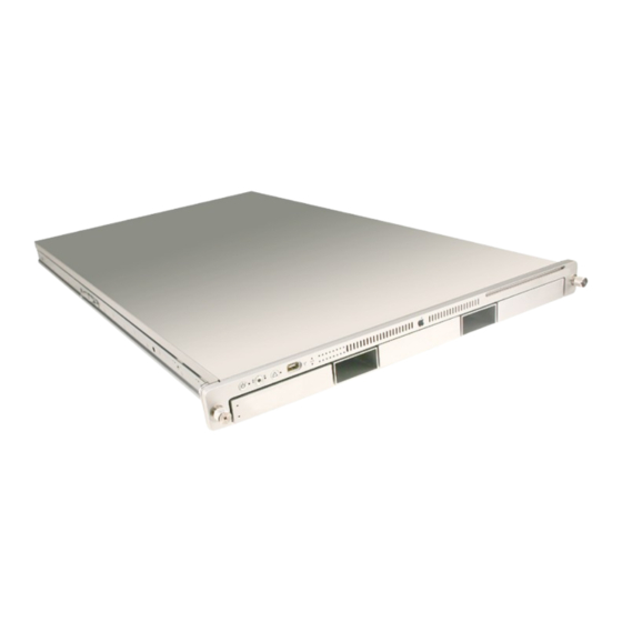
(3) Note: The front bezel of the Xserve (Early 2008) model is identical to the Xserve (Late 2006) image above except the FireWire 400 port is replaced by a USB port, as shown below: On/standby button and light On/standby button and light. - Page 140 Server Monitor. This indicator is useful for locating a particular unit in a rack with more than one Xserve. A second system identifier button and light are on the rear panel.
-
Page 141: Remote Monitoring Software
Xserve and execute these diagnostic tests. Also, using a remote admin computer, you can run tests on either a working Xserve or on a Xserve that does not start up normally. For more information on how to configure and use AXD, please refer to the user’s guide that comes with the diagnostic software. -
Page 142: Symptom Charts
If it does not, realign the logic board. Verify the power outlet is good. Replace the power cord. Disconnect external devices, including the display, and start up the Xserve. Remove both internal PCI riser cards and any installed expansion cards and start up the Xserve. - Page 143 Reseat the FB-DIMMs. Verify that the correct FB-DIMMs are installed. Run Apple Xserve Diagnostics. If the test finds bad memory, replace the FB-DIMMs one at a time and test until all bad FB-DIMMs are replaced with known-good modules. Flashing question mark appears on the connected display Reseat the drive module in the first drive bay.
-
Page 144: Built-In Video
Reseat the mezzanine video card. Clear parameter RAM. Hold down Command-Option-P-R during startup. Reset the SMC. Refer to “Resetting the SMC” in this chapter. Replace the mezzanine video card. Replace the logic board. Xserve (Late 2006) Troubleshooting — Symptom Charts... -
Page 145: Hard Drive Modules
Remove the drive module from the Xserve and inspect it for any damage to its connector or the connector in that drive bay of the Xserve. Do not re-install the drive module if its connector is damaged or if the drive bay connector in the Xserve is damaged. If there is any visible damage, replace the damaged component. -
Page 146: Usb Devices
Verify the disc is not in use by the system. Drag the disc icon to the trash or select it and press Command-E. Connect a USB mouse and restart the Xserve while holding down the mouse button to attempt to eject the disc. -
Page 147: Firewire Devices
(You can also use System Profiler to verify USB ports.) Relaunch Finder. Start up from the system installation disc or system restore disc that came with the Xserve. If the keyboard operates, reinstall system software. Replace the keyboard. -
Page 148: Network Problems
If only one Ethernet port is in use, verify that it is the lower port. If it is not, move the Ethernet cable to the lower port. Boot the Xserve from the Installation disc. Go to another computer on the same subnet and start Server Assistant. If the Xserve can be seen, the Xserve hardware should be functioning correctly. -
Page 149: Views
Service Source Views Xserve (Late 2006) © 2006, 2007, 2008 Apple Inc. All rights reserved. -
Page 150: Internal Views
Internal Views Exploded View 1: Xserve (Late 2006) Top Cover 922-7866 Front Panel Board Cable 922-7857 Airflow Duct 922-7867 Fan Array 076-1248 Drive Interconnect Backplane 661-4188 Backplane-to-Logic Board Cable 922-7864 Power Distribution Board Cable 922-7859 Expansion Cards 661-4047 661-4048 661-4197... -
Page 151: Exploded View 2: Xserve (Late 2006)
Exploded View 2: Xserve (Late 2006) Logic Board 661-4187 Locking Rod 922-6328 ID Tab Front Panel Board 076-1252 922-7853 Enclosure 076-1250 Front Bezel Power Supply 922-6354 661-4196 Front Button Kit 076-0997 Optical Drive Cable 922-7858 Light Pipe Kit 076-0984 Optical Drive... -
Page 152: Exploded View 1: Xserve (Early 2008)
Exploded View 1: Xserve (Early 2008) Top Cover 922-8479 Front Panel Board Cable 922-7857 Airflow Duct 922-8477 Fan Array 076-1286 Drive Interconnect Backplane 661-4648 Backplane-to-Logic Board Cable 922-8475 Power Distribution Board Cable 922-8474 Expansion Cards 661-4197 661-4195 Power Distribution Board... -
Page 153: Exploded View 2: Xserve (Early 2008)
Exploded View 2: Xserve (Early 2008) Logic Board 661-4631 Locking Rod 922-8478 ID Tab 076-1288 Front Panel Board 922-7853 Enclosure 076-1283 Front Bezel Power Supply, 750w 922-8476 661-4650 Optical Drive Cable 922-8545 Light Pipe Kit 076-1287 Optical Drive Hard Drive... -
Page 154: External Views
(3) status light Note: The front bezel of the Xserve (Early 2008) model is identical to the Xserve (Late 2006) image above except the FireWire 400 port is replaced by a USB port, as shown below: Xserve (Late 2006) Views... -
Page 155: Rear View
(pullout tab) Note: The rear panel of the Xserve (Early 2008) and Xserve (Late 2006) model is identical to the image above except you might notice differences if a power supply blank is installed or one or more expansion cards are installed. -
Page 156: Appendix
Service Source Appendix Xserve (Late 2006) © 2006, 2007 Apple Inc. All rights reserved. -
Page 157: Reference For Internal Sensors
Reference for Internal Sensors Xserve (Late 2006) — Reference for Internal Sensors... - Page 158 Xserve (Late 2006) — Reference for Internal Sensors...
- Page 159 Xserve (Late 2006) — Reference for Internal Sensors...
- Page 160 Xserve (Late 2006) — Reference for Internal Sensors...
- Page 161 Xserve (Late 2006) — Reference for Internal Sensors...
- Page 162 Xserve (Late 2006) — Reference for Internal Sensors...
- Page 163 Xserve (Late 2006) — Reference for Internal Sensors...
- Page 164 Xserve (Late 2006) — Reference for Internal Sensors...
- Page 165 Xserve (Late 2006) — Reference for Internal Sensors...
Need help?
Do you have a question about the Xserve and is the answer not in the manual?
Questions and answers