Table of Contents
Advertisement
Quick Links
Advertisement
Table of Contents

Summary of Contents for Dipl.Ing. Klaus Bemmerer AT- 615B
- Page 1 1.5 kW Automatic Remote Controlled Balanced Antenna Tuner Model AT- 615B Short Form Manual 10/2010 Dipl.Ing. Klaus Bemmerer RF Communication Electronics Niendorf-Middeldor 11 23769 Fehmarn GERMANY Phone +49 4371 869145 Fax +49 4371 869154 www.hamware.de eMail: service@hamware.de...
- Page 2 Antenna Tuner System AT-615B Description This tuner is designed to match remotely, balanced HF antennas. This unit features automatic selection of tuner settings based upon transmitted frequency. Unique to this tuner, no special cabling or adapters are required. The operator simply transmits into the antenna and the tuner detects the transmitted frequency and selects the correct settings from memory.
-
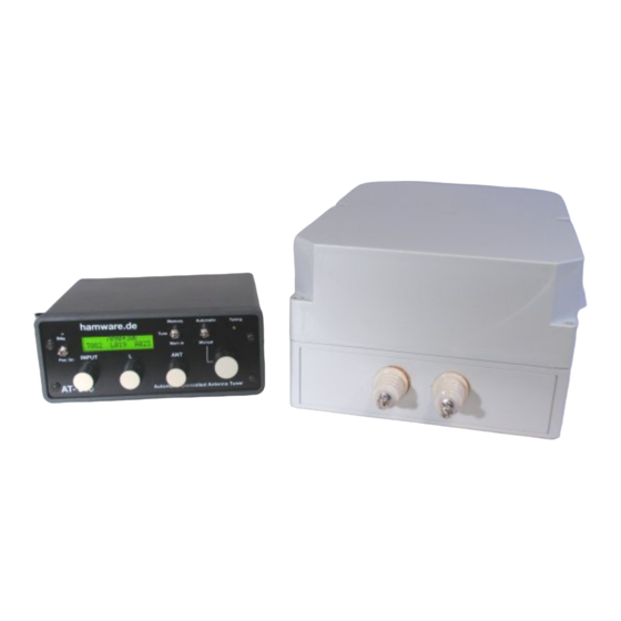
Page 3: Controller Unit
Controller Unit: Antenna matches are stored into a bank of 85 memory locations. Each memory location is a fraction of an amateur band. Refer to the technical section for the fractional segments for each band. As shown in the picture below, the upper line of the LCD shows the actual memory location chosen (lower edge frequency 1840 kHz) with its span (20 kHz). - Page 4 Controller Connections (Rear Side) RF Probe 25-pin. Control Cable to Tuner Unit If the Memory Erase Button is pressed, all memory locations associated with the band indicated on the LC Display will be erased Cinch-Connectors to Power Supply loop-in the key line of Power Amp RF Probe Installation The connection to...
- Page 5 RF Unit: The RF Unit is contained in a weather-protected cabinet (IP66) and is UV resistant. There are two feed-thru insulators to connect to the antenna elements. The coaxial cable and the control cable are connected via a N and a 25 pin connectors. There is no active circuitry inside the RF Unit.
-
Page 6: Installation Of The Rf Unit
Installation of the RF Unit The weather proof cabinet has 6 mounting holes. 6 Befestigungsbohrungen 5 mm The backside of the cabinet should be mounted on a flat surface. Hole spacing is 13.62”H x 9.41”W (346mm x 239mm) Connect the ground bolt between the two antenna insulators with the lightning rod. -
Page 7: Control Cable
Control Cable With a 25conductor (AWG22) wire control cable, the RF Unit can be controlled within a length of 120ft. (40 meters). Lengths in excess require larger wire diameters. Cable shield is not necessary. 10 9 6 5 4 DB-25 Controller Plug View upon selder side of the plug Anschluss der HF-Einheit Blick auf die Lötseite der... -
Page 8: Antenna Descriptions And Design Hints
Antenna Descriptions and Design Hints The remote controlled matching system AT-615B is capable of matching symmetrical antennas from a minimum length of 62 ft. within a frequency range of 1.8 to 30 MHz. The antenna length is dictated by the space available rather than the usual resonant length. It easily covers all amateur bands (including WARC) using a single wire dipole without traps. - Page 9 Some baseline rules for matching “random“ antenna lengths to specific frequencies or frequency bands: Tuner ● If the antenna is fed via a balanced feeder (ladder, twin lead etc.) the value of the relation L should be more than 2/1 Feeder ●...
- Page 10 Antenna Matching (a way to start) - Set the Mode switch to “Manual” - Starting in the 14 MHz band - Turn the Memory selection rotary switch to the indicated memory location “14000 +30k” - Set the transmitter frequency to 14015 kHz (half the span of the memory location). Do not exceed a power level of 200 Watts.
- Page 11 Table of Programmed Memory Cells (Memory Allocations) 160m Band 30m Band Memory Cell Center Freq. Memory Cell Center Freq. 1800+20k 1810 10100+30k 10115 1820+20k 1830 10130+30k 10145 1840+20k 1850 1860+20k 1870 20m Band 1880+20k 1890 14000+30k 14015 1900+20k 1910 14030+30k 14045 1920+20k 1930...
- Page 12 Operating with Power amplifier - Preferably start with 14 MHz or 7 MHz. To recall the appropriate tuning values from the memory place the Tune/Memory switch in Memory position and select the appropriate frequency cell. Check the adjustment for lowest reflected power. - Switch on the power amplifier and set the Output power to approximately 200 Watts.
-
Page 13: Technical Specifications
Technical Specifications RF Unit Frequency Range Amateur Bands 1.8 to 30 MHz Matching Circuit balanced pi filter Input capacitors in 256 steps, 17 pF ea. Inductivities 32 steps exponential increasing 0,2 µH to 35 µH variable output capacitor 400 pF tuned by stepper motor with 200 steps of 0.9°... - Page 14 “Thru” Function Input switched directly to Output Displays - LCD Display indicating single steps for input C, L and output C - Frequency Memory Location - Standby LED - LED while tuner is matching Power +15VDC, 1.5A and +36VDC, 0.5A Metal Bench Cabinet W x D x H = 11 x 3.5 x 6.9 inches Weight...
Need help?
Do you have a question about the AT- 615B and is the answer not in the manual?
Questions and answers