
Related Manuals for socomec iPDU

Summary of Contents for socomec iPDU
- Page 1 Advanced Power Distribution Unit Version 1.0 Installation and operating manual Manuel d’installation et d’utilisation Manuale di installazione e uso...
-
Page 2: About This Manual
SOCOMEC UPS retains the full and exclusive ownership rights over this document. Only a personal right to utilize the document for the application indicated by SOCOMEC UPS is granted to the recipient of such document. All reproduction, modification, dissemi- nation of this document whether in part or whole and by any manner are expressly prohibited except upon Socomec’s express... -
Page 3: Table Of Contents
2. INTRODUCING IPDU ........ -
Page 4: Safety Precautions
• Before maintenance, repair or shipment, the unit must be completely switched off and unplugged and all connections must be removed. • Before plugging in the device power cable, make sure the power source rating matches the power rating of the iPDU. • Use a standard power cable when connecting any device to the iPDU outlets. -
Page 5: Introducing Ipdu
Users can control the on/off power supply for any device connected to the iPDU remotely, using a console or Ethernet connections. The iPDU comes with twelve power outlets, each of which can be monitored and controlled through a console or web interfaces. -
Page 6: Package Contents
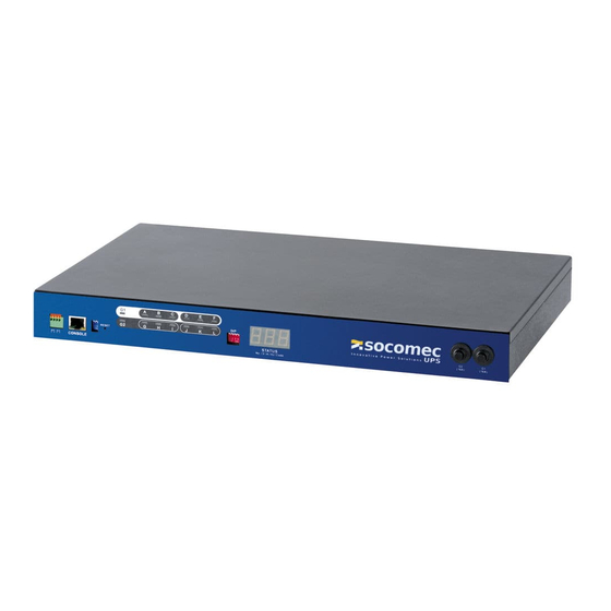
2. INTRODUCING iPDU 2.2. Package Contents Make sure the iPDU package has the following items. If any of the items is missing or damaged, contact your nearest service centre or retailer. 2.2-1 1. iPDU 2. Ears (x2) 3. U-type handles (x2) 4. - Page 7 9. Breaker Prevents excessive current flow to protect the system. Status indicators The front panel of the iPDU has several LED indicators that provide information about the input and output power status. The following table describes these status indicators. Status indicator...
- Page 8 Note: Three outlets group into one unit and the maximum load is 10 Amps for one unit or one outlet. 3. Daisy-chaining (C-link) port Enables users to cascade next iPDU II through an USB cable. 4. Ethernet (LAN) port Enables users to configure the iPDU through a LAN or WAN...
-
Page 9: Getting Started
Read this section carefully to learn how to connect various devices to the iPDU. 3.1. Attaching the feet The iPDU comes with four feet or spacers that are attached to the bottom. Use the four screws provided with the feet to attach them to the bottom of the iPDU as shown: Note: Users do not need to attach the feet if the iPDU is going to be installed in a rack. -
Page 10: Making Connections
EMD to the console port. 2. To configure the iPDU, users can use the console or LAN port. Connect the iPDU to a console and a LAN to enable its configura- tion via the console or browser menu. -
Page 11: Connecting Input Power
3.5. Connecting Input Power The 2-inlet model of the iPDU has two IEC C20 power inlets for supplying and managing power for the output devices. The 1-inlet model has just one inlet for supplying power to all outlets. For each inlet, connect the power cable to the power inlet and plug the other end into a power outlet as shown: 3.5-1... -
Page 12: Connecting Emd
An Environmental Monitoring Device (EMD) that is connected to sensors for detecting temperature, humidity, water leaks etc. can be connected to the iPDU with the console port. The EMD can also be connected to alarms or indicators and controlled through the iPDU. -
Page 13: Connecting The Console
The iPDU has a graphic user interface that allows users to control the device through a web browser. Connect the iPDU to a free port on the router using an Ethernet cable as shown. Users can then control the iPDU from a PC, laptop, mobile phone, or PDA which is connected to the router network. -
Page 14: Daisy Chaining
1. For each iPDU that you add to the chain, use USB cables to connect it to the parent iPDU’s C-Link Port. The upper C-Link port ) of child iPDU II is connected to lower C-Link port (... - Page 15 3. GETTING STARTED Manual mode: Use DIP switches on the front panel to set the (daisy chain) ID number for each iPDU that you add to the chain. You may set Daisy Chain ID for the first unit (Master) to 0 (DIP Switches: On, On, On, On) and the ID for the second unit (Slave 01) to 1(DIP Switches: On, On, On, OFF), etc.
- Page 16 3. GETTING STARTED All the iPDU and connected devices in the daisy chain can be controlled through the web interface. iPDU - Ref.: IOMPDUXXXX02-GB 00...
-
Page 17: Using The Console Menu
Use the serial cable provided to connect the console port to the PC’s COM port as described in Connecting the Console on page 13. This section describes how to use a console application to control the iPDU and configure its settings such as the IP address, outlet control parameters, access control table, and trap receivers table. -
Page 18: Navigating Through The Console Menu
This menu also provides the option under the control group submenu to enable input phase detection which allows the iPDU to turn off outlet power if there is a phase mismatch. -
Page 19: Using The Web Interface
5.1. Overview Start a web browser such as Internet Explorer from the host PC or laptop and enter the IP address of the iPDU in the address bar. For details about setting the IP address of the system see Setting the IP Address on page 18. You will be prompted to enter a Username (admin) and Password (default password is public). -
Page 20: Modifying The Basic Settings
5. USING THE WEB INTERFACE 5.2. Modifying the Basic Settings The System menu enables users to configure the iPDU system parameters such as the administrator name, password, IP address, date, time etc.. Some of these settings have been described here for users’ reference. -
Page 21: Modifying Application Settings
5.3.1. Setting Control Options Click Control under Power Management to display the control options for the power. • Inlet: Specify what action is taken by the iPDU when the inlet voltage is not within limits. Users can set which power outlets and digital outputs are to be turned on or off when the inlet voltage is not acceptable value. - Page 22 5.3.4. Confi guration Click Configuration under Environment menu to configure the EMD connected to the iPDU. This menu enables users to set up the sensor names, high and low set points, calibration offsets for the sensors, as well as alert names and normal conditions.
- Page 23 5.3.6. Confi gure the Power-On/Off Sequence iPDU allows users to configure the sequence in which power is turned on or off for each outlet. To manage the Power-On Sequence, set appropriate delay time in Power On Delay field for each outlet in the Control webpage under Power Management as illustrated in the following figure.
-
Page 24: Appendix
6. APPENDIX 6.1. Specifi cations The specifications for iPDU II-1202 (2-inlet models of the iPDU ) and iPDU II-1201 (1-inlet models of the iPDU) are listed as follows: iPDU II-1202 (2-inlet models of the iPDU) Model iPDU II -1202 -120V... -
Page 25: Error Codes
Outlet I Current Over Threshold (Amp) Outlet J Current Over Threshold (Amp) Outlet K Current Over Threshold (Amp) Outlet L Current Over Threshold (Amp) Input Source Abnormal (Should be 120v Model) Input Source Abnormal (Should be 230v Model) iPDU - Ref.: IOMPDUXXXX02-GB 00... -
Page 26: Regulatory Information
6.3.3. CB and TUV The product is accredited with IEC 60950-1 and EN 60950-1, for use in Information Technology Equipment, including Electric Business Equipment. The TUV Recognition or CB certification is remains throughout the product's lifetime. iPDU - Ref.: IOMPDUXXXX02-GB 00... - Page 28 SALES, MARKETING AND SERVICE MANAGEMENT SOCOMEC GROUP SOCOMEC UPS Paris S.A. SOCOMEC capital 11 149 200 € - R.C.S. Strasbourg B 548 500 149 95, rue Pierre Grange B.P. 60010 - 1, rue de Westhouse - F-67235 Benfeld Cedex F-94132 Fontenay-sous-Bois Cedex - FRANCE Tel.
Need help?
Do you have a question about the iPDU and is the answer not in the manual?
Questions and answers