Table of Contents
Advertisement
Quick Links
Save This Manual for Future Reference
Original Instruction
Questions: E-mail Support@powrkraft.com
Before starting the engine,
check engine oil level and
ensure the engine is filled as
described in the Engine Manual.
2-Stage Snow Thrower
Operator's Manual
MODEL NUMBER :o PK30255L o PK30265L
SERIAL NUMBER : ________________________
Both model number and serial number may be found on the main
label. You should record both of them in a safe place for future use.
FOR YOUR SAFETY
READ AND UNDERSTAND THE ENTIRE MANUAL BEFORE
OPERATING MACHINE
Advertisement
Table of Contents

Summary of Contents for Pow’R’kraft PK30255L
-
Page 1: Serial Number
Engine Manual. 2-Stage Snow Thrower Operator’s Manual MODEL NUMBER :o PK30255L o PK30265L SERIAL NUMBER : ________________________ Both model number and serial number may be found on the main label. You should record both of them in a safe place for future use. - Page 2 Your snow thrower has many features that will TABLE OF CONTENTS make your faster easier. Safety, performance, and dependability have been given Introduction to top priority in the development of this machine, Environmental making it easy to maintain and operate. Symbols Safety General Safety Rules...
- Page 3 Keep bystanders away. Be thoroughly familiar with the controls and their proper operation. Know how to stop the machine Stop engine and remove ignition and disengage the controls quickly. key prior to leaving the operator’s position. Make sure to read and understand all the instructions and safety precautions as outlined in Only use clean-out tool to clear the Engine Manufacturer’s Manual, packed...
- Page 4 Check your machine before starting it. Keep Fuel safety guards in place and in working order. Make sure all nuts, bolts, etc. are securely tightened. Fuel is highly flammable, and its vapors can Disengage all clutches and shift into neutral before explode if ignited.
- Page 5 and wipe up spilled fuel. Never operate the unit Do not put hands or feet near rotating parts. without the fuel cap securely in place. Avoid contact with hot fuel, oil, exhaust fumes and Avoid creating a source of ignition for spilled fuel. hot surfaces.
- Page 6 or these instructions to operate it. Machine is embankments. Machine can suddenly turn over if dangerous in the hands of untrained users. a wheel is over the edge of a cliff or ditch, or if an edge caves in. Service Before cleaning, repair, inspecting, or adjusting Keep all bystanders, children, and pets at least shut off the engine and make certain all moving...
- Page 7 When parking on a slope, always block the inspections. wheels. Hand contact with the rotating parts inside the Disengage power to the auger when transporting discharge chute is the most common cause of or not in use. injury associated with snow throwers. Do not unclog chute assembly while engine is running.
- Page 8 1. Snow Thrower Unit 2. Discharge Chute 3. Handlebars 4. Lower Handle 5. Long Chute Rod 6. Shift Rod 7. Operator’s Manual & Engine Manual 8. Engine Hardware Bag 9. Snow Thrower Hardware Bag, including and secure the handlebars with M8X45 screws, ASSEMBLY washers and nuts until they are finger tight.
- Page 9 may cause tire/rim assembly to burst with force sufficient to cause serious injury. Refer to side wall of tire for recommended pressure. Equal tire pressure should be maintained at all times. If the tire pressure is not equal in both tires, the machine may not travel in a straight path and the scraper blade may wear unevenly.
- Page 10 9. Release the lock latch on the gear assembly and turn the discharge chute straight ahead. 10. To ensure the discharge chute and chute 6. Remove the gear cover by removing the two deflector follow their full range of travels, ST4.8X13 self-tapping screws.
- Page 11 roll pin through the holes. 2. After the shift rod with a flat washer has been inserted through the hole in the shift arm, add the other flat washer on the shift rod, and secure with a clevis pin. 15. Hold the trigger cap down and rotate the joystick in a circle to ensure the that the discharge chute and chute deflector operate smoothly.
- Page 12 place until needed. Battery (if so equipped) 1. Remove the battery cover by loosening the screw and nut. Connect positive (red) battery cable to the battery terminal first, then negative (black) battery cable. Check that all cable connectors are tight. Install battery cover and tighten the screw and nut.
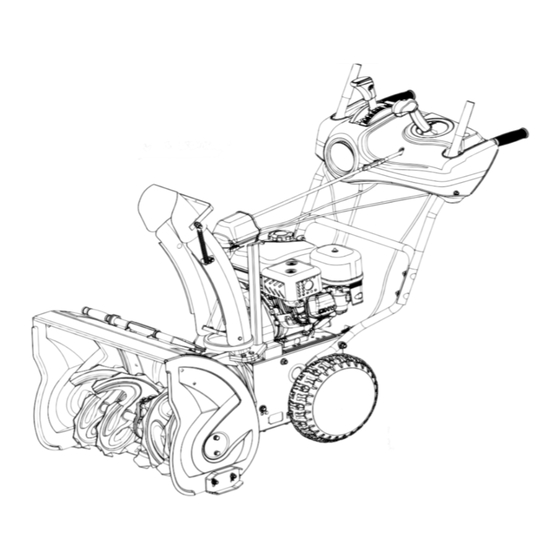
- Page 13 KNOW YOUR MACHINE Features and Controls 2-STAGE SNOW THROWER Revision 3-12-14...
- Page 14 2-STAGE SNOW THROWER...
- Page 15 Speed Shift Lever 4-Way Chute Directional Control The speed shift lever has 8 positions: 6 forward speeds and 2 reverse. To change speeds, move the speed shift lever to the desired position. The lever locks in a notch at each speed selection. Always release the drive clutch lever before changing speeds.
- Page 16 Always release the drive clutch lever Shear Pins before changing speeds. Failure to do so will result in damage to the snow thrower. The augers are secured to the auger shaft with shear pins and clevis pins. If the auger should strike a foreign object or ice jam, the snow Auger Clutch Lever thrower is designed so that the pins may shear,...
- Page 17 The chute clean-out tool is conveniently fastened so they face forward as shown. Wing nuts should to the rear of the auger housing with a mounting be fastened on the outside of the auger housing. clip. Should snow and ice become lodged in the discharge chute during operation, proceed as follows to safely clean the discharge chute and chute opening:...
- Page 18 Engage choke by rotating lever to FULL position whenever you are starting a cold engine. As engine warms up, gradually rotate the choke to the OFF position. Do not use choke to start a warm engine. Never use choke to stop engine. Primer Press the primer to pump additional fuel from the Steering Triggers...
- Page 19 Thoroughly inspect the electrical cord snow conditions. before using the machine. If the cord is Adjustments damaged, do not operate the machine. Replace or repair the damaged cord immediately. Skid Shoes Connect extension cord to the electric Position the skid shoes based on surface starter plug-in first and then to a power conditions.
- Page 20 2. Make sure the entire bottom surface of skid shoe is against the ground to avoid uneven wear on the skid shoes. 3. Retighten nuts and bolts securely. Auger Clutch and Drive Clutch When the auger clutch lever or drive clutch is released and in the disengaged position, the cable should have very little slack.
- Page 21 Deflector Control If deflector does not follow full range of travel, adjust the control cable at either end of it 1. Hold the trigger cap down and push joystick all the way forward. Release the trigger cap. 2. Loosen adjusting nuts on cable support bracket either underneath the control panel or on the chute deflector.
- Page 22 J Bolt Flange Lock Nut Track Side Plate Front Track Idler Wheel Operation Freewheeling and Self-Propelling Starting and Stopping the Engine Use the axle lock pin to lock or unlock the right or left wheel. Lock both wheels to increase traction; unlock one wheel to allow for easier turning of the Before starting the engine, check engine unit;...
- Page 23 above 10 C (50 F), priming is not necessary. Some snow engine is not equipped with primer as priming is not needed for such Over priming may cause flooding, engine. preventing the engine from starting. If you do flood the engine, wait a few minutes 4.
- Page 24 Stop the engine, wait for all moving parts to stop, Allow the engine to warm up for a few and remove all ice and snow from the snow minutes, Engine will not develop full thrower. With the engine off, pull the recoil starter power until it has reached normal handle several times to prevent the recoil starter operating temperature.
- Page 25 Lubrication Auger Gearbox The gearbox was filled with lubricant to the proper level at the factory. Unless there is evidence of leakage or service has been performed on the gearbox, no additional lubricant should be required. If lubricant is required, use GL-5 or GL-6, SAE85-95, EP gear oil lubricant.
- Page 26 cable. cover in place and set the cover aside 7. Place the battery on the tray and Install the cover Off-Season Storage Refer to the Engine Manual for information on storing your engine. At the end of the season or if the snow thrower will not be used for 30 days longer, follow the storage instructions below.
- Page 27 7. Replace the auger belt(s) by following instructions in reverse order. Drive Belt If the drive belt becomes worn, oil-soaked, or otherwise damaged, proceed as follows to replace the belt. 1. To prevent spillage, remove all fuel from tank 6. Remove the belt(s) from around the auger by running engine until it stops.
- Page 28 a. Roll the auger belt off the engine pulley. b. Pivot the idler pulley toward the right to relieve tension. 7. Remove and replace belt in the reverse order. c. Lift the drive belt off engine pulley. 4. Carefully pivot the snow thrower up and Holding down the drive clutch lever will forward so that it rests on the auger housing.
- Page 29 rod. 4. Remove bottom cover to avoid bending it when tipping unit apart. 5. Remove the screws securing auger housing to the frame (two on each side). Tip auger housing and frame apart. 6. Replace auger belt or drive belt. 7.
- Page 30 Remove the other snap ring from the right-hand side of the hex shaft. Carefully position the hex shaft downward and to the left before carefully sliding the friction wheel assembly off the shaft Carefully position the hex shaft downward and to the left before carefully sliding the friction wheel assembly off the shaft On tracked model, remove the hex nut and lightly...
-
Page 31: Trouble Shooting
3. Reassemble the side plates with a new rubber ring. When reassembling the friction wheel assembly, make sure that rubber ring is centered and seated properly between the side plates. Tighten each screw only one rotation before turning the wheel clockwise and proceeding with the next screw on the other side of the wheel. - Page 32 Engine fails to start 1. Choke not in CHOKE position. 1. Move choke to CHOKE position. 2. Engine not primed. 2. Prime engine as instructed in this 3. Engine is flooded. manual. 4. Fuel shut-off valve closed. 3. Wait a few minutes before 5.
- Page 33 6. Throttle not in FAST position 6. Move throttle to FAST position. when throwing snow. 7. Shift into a lower gear. 7. Moving too fast to clear the 8. Reduce speed and width of swath. snow. 9. Do not overload with extremely 8.
- Page 34 2-STAGE SNOW THROWER...
- Page 35 2-STAGE SNOW THROWER Revision 3-12-14...
- Page 36 2-STAGE SNOW THROWER...
- Page 37 Parts Request Form Fax to 541‐895‐2756 or E‐mail Parts@PowRkraft.com Name: Model Number: Address: Serial Number: City State Zip: Purchased From: Phone: Purchase Date: E‐mail: Item No. Description Price Amount Comments: 2-STAGE SNOW THROWER Revision 3-12-14...
- Page 38 Betst Products, LLC. Pow’R’kraft LIMITED WARRANTY & REGISTRATION FORM Betst Products, llc. warrants to original Purchaser that Pow’R’kraft products are free from major defects in material under normal use and service for a period of Two (2) Years from the date the product is shipped. Unless otherwise stated in the materials that arrive with your product, all other products we offer are protected against defects in materials and workmanship, under ordinary and normal use, for a period of one year from its shipping date.
- Page 39 Revision 7-29-13 WARRANTY VOID IF REGISTATION IS NOT RECEIVED OR RECORDED ONLINE WITHIN 30 DAYS OF PURCHASE DATE REGISTRATION Item________________________________Model # _________________ Purchase Date_____/_____/_______ Purchased From: ____________________________________ Inv#/Order# ____________________________ Owner Name: _______________________________________ Owner Address: _______________________________________ City: ________________________ County: ___________ ST: ______ Zip Code: _____________ Phone: _______________________ Email: ________________________ Acceptance of responsibility: I (Purchaser) have read operators manual and Limited Warranty or someone has read/and explained all...
- Page 40 2 YEAR EXTENDED WARRANTY & REGISTRATION Pow’R’Kraft Branded Products 2 YEAR EXTENDED WARRANTY 2 Year Extended Warranty amends to original Recorded Warranty Registration the time period of described coverage. Extended Warranty does not apply to Consumable and Expendable Items as described in Product Warranty Registration. This Amendment does not affect any other part of recorded Warranty Registration or Policy.
Need help?
Do you have a question about the PK30255L and is the answer not in the manual?
Questions and answers
where do i get parts from? i need the cable to engage the drive
The drive clutch cable for the Pow’R’kraft PK30255L can be adjusted at either end of its control cables. You can find it near the drive clutch lever and the cable support bracket.
This answer is automatically generated