Table of Contents
Advertisement
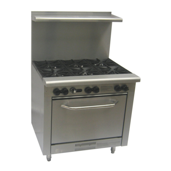
Gas range with oven
(SMDR-36-6)
Operation Manual
Please read it carefully & keep it in a convenient place for reference
Model SMDR-36-6
Saturn Equipment Primoris Inc.
5670 Greenwood Plaza,
Blvd Suite 501 Greenwood Villigae,Colorado
80111-2409
www.ThinkSaturn.com
Gas Range Manual
Page 1
Revision: 24 Feb 2011
Advertisement
Table of Contents

Related Manuals for Saturn SMDR-36-6


Summary of Contents for Saturn SMDR-36-6
- Page 1 Gas range with oven (SMDR-36-6) Operation Manual Please read it carefully & keep it in a convenient place for reference Model SMDR-36-6 Saturn Equipment Primoris Inc. 5670 Greenwood Plaza, Blvd Suite 501 Greenwood Villigae,Colorado 80111-2409 www.ThinkSaturn.com Gas Range Manual Page 1...
-
Page 2: Installation And Operation
INSTALLATION AND OPERATION MANUAL RANGE SERIES WARNINGS IMPROPER INSTALLATION, ADJUSTMENT, ALTERATION, SERVICE OR MAINTENANCE CAN CAUSE INJURY OR DEATH. THE INSTRUCTION MANUAL MUST BE READ CAREFULLY BEFORE INSTALLING, OPERATING OR SERVICING THIS EQUIPMENT TO BE INSTALLED ONLY BY AN AUTHORISED PERSON IN ACCORDANCE WITH AS 5601, LOCAL AUTHORITY, GAS, ELECTRICITY, ANY APPLICABLE STATUTORY REGULATIONS AND MANUFACTURER... - Page 3 THIS EQUIPMENT IS DESIGNED FOR COMMERCIAL CATERING PURPOSES AND WILL GENERATE SIGNIFICANT HEAT. HOT SURFACES WILL CAUSE BURNS. A HAZARD AND RISK ASSESSMENT MUST BE UNDERTAKEN BY OWNERS AND ALL OPERATORS MADE AWARE OF THESE. DO NOT STORE OR USE FLAMMABLE LIQUIDS NEAR THIS APPLIANCE.
- Page 4 CONGRATULATIONS Thank you for choosing this product and welcome you to the ever-growing customer circle. This product has been specifically designed to meet a wide range of applications and represents the best quality and highest value equipment. Please read the instruction manual carefully to ensure the safe and reliable operation and performance of your equipment.
-
Page 5: Table Of Contents
TABLE OF CONTENTS INTRODUCTION ---------------------------------------------------------------------------------------------- 7 GENERAL ------------------------------------------------------------------------------------------------ 7 WARRANTY --------------------------------------------------------------------------------------------- 7 GENERAL INFORMATION -------------------------------------------------------------------------------- 8 INSPECTION -------------------------------------------------------------------------------------------- 8 OPERATOR MANUAL --------------------------------------------------------------------------------- 8 INSTALLATION ------------------------------------------------------------------------------------------ 8 GAS CONNECTION ----------------------------------------------------------------------------------- 8 GAS PRESSURE --------------------------------------------------------------------------------------- 9 COMMISSIONING ------------------------------------------------------------------------------------- 9 SPECIFICATIONS ------------------------------------------------------------------------------------------ 10 INSTALLATION ---------------------------------------------------------------------------------------- 10 GAS INPUT INFORMATION ----------------------------------------------------------------------- 11 GAS SUPPLY PRESSURE ------------------------------------------------------------------------ 11... - Page 6 TABLE OF CONTENTS (continued) SERVICE ........................18 RECOMMENDED SERVICE ................... 18 SERVICE INFORMATION ..................18 OPEN AND GRILL BURNER ADJUSTMENTS ............19 OVEN CONTROL SETTINGS AND ADJUSTMENTS ..........20 CONVERSION INSTRUCTIONS ................21 SPARE PARTS ......................22 TROUBLE SHOOTING ....................23 ALL BURNERS ......................
-
Page 7: Introduction
INTRODUCTION GENERAL The range is designed for commercial catering purposes and incorporates a wide range of design features.. WARRANTY This product is subject to the correct installation, operation, maintenance and care of the equipment. Warranty does not extend to: • Damages caused in shipment •... -
Page 8: General Information
GENERAL INFORMATION Inspection. Please inspect the unit on receipt. If the unit is damaged, contact the carrier immediately and file a damage claim with them. Save all packing materials when filing a claim. Freight damage claims are the responsibility of the purchaser and are not covered under warranty. -
Page 9: Gas Pressure
Gas Pressure. The authorized person installing this equipment must ensure that the gas operating pressure is the same as shown on the rating plate and that there is sufficient gas volume. The unit and its individual shut off valve must be disconnected from the gas supply piping system during any pressure testing of the gas supply piping system at test pressures in excess of 1/2 PSIG (3.45 kPa) Commissioning. -
Page 10: Specifications
Product Product Product Oven Model breadth depth height Burners Qty (inch/mm) (inch/mm) (Inch/mm) SMDR-36-6 36 / 916 33 / 840 59 / 1495 Gas Range Manual Page 10 Revision: 24 Feb 2011... -
Page 11: Gas Input Information
Installation Clearances: The MINIMUM clearance from combustible and noncombustible surfaces is 9” (229 mm) from the sides and 6” (152 mm) from the rear. Adequate clearance must also be provided for service. Levelling: Refer also to ‘Clearances Oven Base’ above. To adjust the legs to level the unit to the floor and/or to slightly adjust the height of the unit, raise the front of the unit and adjust the legs (ensure... -
Page 12: Test Point Pressure
TEST POINT PRESSURE The pressure test point is located on the gas manifold. The gas manifold and pressure test point is accessed by removing the gas valve control knobs and the front panel. The test point pressure is shown in the Nominal Gas Consumption Table. -
Page 13: Operating Instructions
OPERATING INSTRUCTIONS LIGHTING INSTRUCTIONS DO NOT OPERATE THE UNIT UNLESS IT HAS BEEN INSTALLED AND COMMISSIONED BY AN AUTHORIZED PERSON. BEFORE TURNING ON THE MAIN GAS SUPPLY, CHECK AND ENSURE THAT ALL THE VALVES ARE IN THE “OFF” POSITION. THIS EQUIPMENT IS DESIGNED FOR COMMERCIAL CATERING PURPOSES AND WILL GENERATE SIGNIFICANT HEAT. -
Page 14: Open Top Burners
OPEN TOP BURNERS 1. Before attempting to light the appliance, the cover, if so equipped, shall be opened. 2. Make sure all valves are closed before turning on the gas supply. 3. Turn on the pilot valve with a screw driver. Light up the pilot with a flame gun. -
Page 15: Operator Maintenance
OPERATOR MAINTENANCE CONTACT THE FACTORY, THE FACTORY REPRESENTATIVE OR A LOCAL SERVICE COMPANY TO PERFORM MAINTENANCE AND REPAIRS. USE ONLY SUITABLE CHEMICALS AND OBSERVE ALL MANUFACTURER SAFETY REQUIREMENTS FOR SAFE HANDLING AND USE. SEASONING THE GRILL (only applicable if there is a grill) NOTE: The grill surface has protective coating applied at manufacture. -
Page 16: Cleaning Stainless Steel
NOTE: Empty the grease drawer as necessary and clean. Weekly, clean the grill surface thoroughly with a grill pad while the surface is still warm (not hot). After cleaning, ensure any detergent/chemical is thoroughly removed. The grill surface should be covered with a thin film of cooking oil to prevent rusting. -
Page 17: Trivets
If any ports remain clogged, remove the burner cap and complete burner and clean thoroughly with a suitable detergent and hot water. Dry thoroughly, ensure the air shutter is fully open, reinstall (ensure the injector is located in the burner venturi), ignite and check the flame pattern. Note: The burner flame should be uniformly blue. -
Page 18: Service
SERVICE CONTACT THE FACTORY, THE FACTORY REPRESENTATIVE OR A LOCAL SERVICE COMPANY TO PERFORM MAINTENANCE AND REPAIRS. FOR YOUR SAFETY, ALL SERVICE WORK MUST BE CARRIED OUT BY AN AUTHORISED PERSON AND USE ONLY ORIGINAL SUPPLIED AND SPECIFIED PARTS. TEST ALL FITTINGS, PIPES AND PIPE CONNECTIONS FOR LEAKS IN ACCORDANCE WITH APPROVED GAS LEAK TEST PROCESSES AND METHODS. -
Page 19: Open And Grill Burner Adjustments
OPEN AND GRILL BURNER ADJUSTMENTS Leak Test Ensure that all valves are in the OFF position. Turn on the main gas supply valve. Light all pilots. Leak test all valves and fittings using approved methods. Correct any leaks as required and re-check. Shut off all valves and set thermostat dials to “OFF”... -
Page 20: Oven Control Settings And Adjustments
OVEN CONTROL SETTINGS AND ADJUSTMENTS Test Point Pressure The oven burner pressure test point is located also on the manifold test point on the top section. The test point pressure is shown in the Nominal Gas Consumption Table Gas Range Manual Page 20 Revision: 24 Feb 2011... -
Page 21: Conversion Instructions
CONVERSION INSTRUCTIONS TO BE COMPLETED BY AN AUTHORISED PERSON ENSURE GAS IS ISOLATED WHILE PERFORMING CONVERSION WORK. PERFORM A LEAK TEST BEFORE IGNITING AND CALIBRATING BURNER AND PILOT ADJUSTMENTS. TO PROPANE GAS Regulator Change regulator to PROPANE gas configuration and adjust as necessary Open Burner/Grill Burner Access and change the injectors to PROPANE Gas injectors (refer Nominal Gas Consumption Table) -
Page 22: Spare Parts
LEAK TEST IN ACCORDANCE WITH APPROVED METHODS Ignite burners and adjust AMEND DATA PLATE AND APPLY ‘NATURAL GAS’ LABEL SPARE PARTS A list of major spare part items is shown at the end of this manual. Gas Range Manual Page 22 Revision: 24 Feb 2011... -
Page 23: Trouble Shooting
TROUBLE SHOOTING ALL SERVICE WORK TO BE COMPLETED BY AN AUTHORISED PERSON. ALL BURNERS CONDITION CHECK Pilot will not light. Gas supply is on and gas pressure is correct Blocked pilots Pilot adjusting screw Pilot repeatedly goes out. Pilot flame size and position Yellow Burner Flame. -
Page 24: Oven
OVEN Incorrect oven temperature Oven thermostat and control dial position Burner shuts off at set Thermostat/by-pass temperature Gas Range Manual Page 24 Revision: 24 Feb 2011... -
Page 25: Range - Exploded Views,Part List And Gas Diagram
Exploded view (SMDR-36-6) Gas Range Manual Page 25 Revision: 24 Feb 2011... - Page 26 Gas diagram(SMDR-36-6) Gas Range Manual Page 26 Revision: 24 Feb 2011...
- Page 27 Installation of backguard Page 27 Gas Range Manual Revision: 24 Feb 2011...
- Page 28 Page 28 Gas Range Manual Revision: 24 Feb 2011...
- Page 29 Page 29 Gas Range Manual Revision: 24 Feb 2011...
Need help?
Do you have a question about the SMDR-36-6 and is the answer not in the manual?
Questions and answers