Advertisement
Quick Links
Advertisement

Summary of Contents for Major M-360
- Page 1 INSTRUCTION MANUAL M-360 AM / FM / SSB 120 CHANNEL DIGITAL PLL SYNTHESIZED TRANSCIEVER...
- Page 2 Crystal lattice filter mA [SSB] Carrier Suppression [SSB]: 40dB down Current Drain at Maximum Modulation: A [AM] Microphone wiring Microphone connection for Major M360 (Viewed from Solder Side of the plug) Receive Common / Screen Transmit Mic. Audio - 1 -...
- Page 3 Installation Instructions This transceiver is designed for 12 volt DC operation with either a negative or positive ground system. In order to install the radio, it is important to know whether your vehicle has a positive or negative ground system. Connecting the radio incorrectly will damage it. Vehicle's Electrical System We suggest that you check with qualified technician and find out if your make and model vehicle uses a positive ground or negative ground system.
- Page 4 Typical Under-dash installation Connecting to a Positive Ground System Follow the instructions in this section only if you are certain that your vehicle has a positive ground system. Connect the positive (red) wire to a screw or bolt on the metal frame supporting the instrument panel, or to any metal point that is part of the Vehicle's metal structure.
-
Page 5: Operating Instructions
Operating Instructions To Receive 1 Turn the unit on by rotating the Volume control clockwise. Continue to rotate the knob in the same direction to increase the loudness. 2 Turn the Squelch control anti-clockwise, then slowly clockwise until the hissing sounds just stop. It is important to set this control carefully. -
Page 6: Controls And Functions
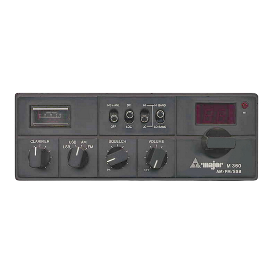
Controls and Functions UK 40 HI BAND SIGNAL 1 3 5 7 9 LO BAND VOLUME CLARIFIER SQUELCH USB AM M 360 AM/FM/SSB S-RF Power Meter This meter shows the relative strength of incoming signals when receiving, and RF power output when transmitting. - Page 7 Controls and Functions (Cont’d) UK 40 HI BAND SIGNAL 1 3 5 7 9 LO BAND VOLUME CLARIFIER SQUELCH USB AM M 360 AM/FM/SSB Clarifier The Clarifier adjusts the frequencies of the Transmitter and receiver very slightly in order to ensure that Sideband [USB or LSB] signals are heard correctly.
- Page 8 Operating Frequencies “Mids” “Highs” CEPT Std. ‘Freeband’ 27.555 “LO BAND” “HI BAND” “HI BAND” “LO” or “HI” “LO” “HI” 26.965 27.215 27.415 27.665 27.865 28.115 26.975 27.225 27.425 27.675 27.875 28.125 26.985 27.255 27.435 27.705 27.885 28.155 27.005 27.235 27.455 27.685 27.905 28.135...

