Table of Contents

Subscribe to Our Youtube Channel
Summary of Contents for Rocktron PatchMate LOOP 8
- Page 1 MANUAL May be covered by one or more of the following: U.S. Patents #4538297, 4647876, 4696044, 4745309, 4881047, 4893099, 5124657, 5263091, 5268527, 5319713, 5333201, 5402498 and 5493617. Other patents pending. Foreign patents pending.
-
Page 2: Specifications
Your PatchMate LOOP 8 has been designed to comply with the following Standards and Directives as set forth by the European Union: Council Directive(s): 89/336/EEC, 73/23/EEC, 76/769/EC, 1994/62/EC, 2000/ 53/EC, 2002/95/EC Standard(s): EN55022, EN50082-1, EN60065 This means that this product has been designed to meet stringent guidelines on how much RF energy it can emit, and that it should be immune from other sources of interference when properly used. - Page 3 PRECAUTIONS NOTE: IT IS VERY IMPORTANT THAT YOU READ THIS SECTION TO PRO- VIDE YEARS OF TROUBLE FREE USE. THIS UNIT REQUIRES CAREFUL HAN- DLING. • All warnings on this equipment and in the operating instructions should be adhered to and all operating instructions should be followed. •...
- Page 4 PatchMate LOOP 8 The PatchMate LOOP 8 is easy to set up and program with real time user controls. Program the unit from the front panel using the lighted buttons. Recall presets using MIDI program changes. Control any LOOP in real time using MIDI Continuous Controllers.
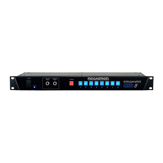
- Page 5 PatchMate LOOP 8 Front Panel 1 POWER Switch and LED Use this switch to turn on and off the PatchMate LOOP 8. When the LED is lit the power will be ON. When the LED is out, the power is OFF..
- Page 6 2 LOOP Section Number "2" These jacks are used to connect your second device in the signal chain. These jacks correspond to the LOOP Button Number "2" on the front panel of the PatchMate LOOP 8. 3 LOOP Section Number "3"...
- Page 7 Use this jack to plug in your MIDI controller. This jack is a 7 Pin MIDI Jack, however a stan- dard 5 Pin MIDI Cable can be used. If plugging into a Rocktron MIDI controller such as the All Access, MIDI Mate or MIDI Xchange, we recommend using the Rocktron RMM900 7-Pin MIDI Cable (sold separately).
- Page 8 Individual LOOP Jacks Descriptions 1 IN Jack This is the first jack in the signal chain. The audio signal will enter the "LOOP" through this jack. 2 SEND - N.C. Jack This jack is used to send the signal to the desired audio device. 3 RETURN Jack This jack is used to receive the returned signal from the desired audio device..
- Page 9 Connections This connection diagram shows one way to use the LOOPs in the PatchMate. Although only two con- nections are shown here, you can follow a similar progression of connects using LOOPs 3-8.
- Page 10 Connections..continued..This connection diagram shows one way to use the LOOPs in the PatchMate to connect stompboxes (pedals). Although only two connections are shown here, you can follow a similar progression of con- nects using LOOPs 3-8.
- Page 11 Connections..continued..This connection diagram shows one way to use the LOOPs in the PatchMate to connect to multiple ef- fects processors.
- Page 12 Connections..continued..This connection diagram shows one way to use the LOOPs in the PatchMate to connect to two different preamp. OUT - N.O. RETURN SEND - N.C. �� �� ���� � ��� �� �� �� ��� �� ���� ���� ������ � ������...
- Page 13 Connections..continued..This connection diagram shows one way to use the LOOPs in the PatchMate to connect two amplifiers and select between the two.
- Page 14 Connections..continued..This connection diagram shows one way to use the PatchMate's buffered connection.
- Page 15 Connections..continued..This connection diagram shows one way to use the PatchMates buffered connection to connect to two different preamps.
- Page 16 Connections..continued..This connection diagram shows one way to connect the PatchMate to "MUTE" an effects processor where parallel effect routings are being implemented.
- Page 17 Note: Internal PHANTOM POWER is provided by the PatchMate Loop 8 via the MIDI IN connector pins 6 & 7 and will power your Rocktron MIDI Controller eliminating the need to have a power adatper plugged directly into the MIDI Controller.
- Page 18 Setup your PatchMate: To setup your PatchMate please follow these instructions. 1. Press and hold the STORE BUTTON until it begins blinking then release it to enter the MIDI CON- FIGURATION PROGRAMMING MODE. 2. The Front panel will be displaying the current MIDI CHANNEL configuration information. To modify the MIDI CHANNEL information press the desired button combination.
- Page 19 MIDI Channel Select...
- Page 20 MIDI Controller Setup 3. The FRONT PANEL BUTTONS [ 1 thru 8 ] will blink twice and the STORE BUTTON will start blinking faster signifying that the MIDI CONTROLLER information is now being displayed. 4. You may now make your selections or you may PRESS CANCEL [ 6 ] ON then PRESS and RE- LEASE the STORE BUTTON .
- Page 21 MIDI Controller Setup *CANCEL: PRESS SWITCH 6 then PRESS and RELEASE the STORE BUTTON to CANCEL the PROGRAM- MING MODE. Note: If CANCEL is executed any modified information will not be retained. STEREO LINK: When selected BUTTONS 1-4 will become the control over the linked pairs. [ 1 to 5 ] [ 2 to 6 ] [ 3 to 7 ] [ 4 to 8 ].
- Page 22 3) PRESS and RELEASE the STORE BUTTON to execute a dump of all user preset data via MIDI. The STORE BUTTON will blink rapidly during this process. After the PatchMate LOOP 8 has finished the Midi Preset Dump process the PROGRAMMING MODE will be canceled and the PatchMate LOOP 8 will return to the current PRESET.
- Page 23 Make sure you have exited the MIDI CONFIGURATION PROGRAMMING MODE before using your PatchMate LOOP 8 with a Midi Controller. 1. Connect your Midi Controllers MIDI OUT to the PatchMate LOOP 8’s MIDI IN using a 5 PIN MIDI cord.
- Page 24 Setting the PatchMate using MIDI Program Changes..continued..On the initial reception of this ON state value the target relay will be activated followed by the execu- tion of the delay release timer. Note: When this feature is being used any transmitted value of 0 will be ignored as the delay will handle the off state execution.
- Page 28 Rocktron -A Division of GHS Corporation 2813 Wilber Avenue Battle Creek MI 49037 Rocktron Phone: 1-(269)-968-3351 Email: info@rocktron.com Check us out on the web at: www.rocktron.com 2008-0001 Rev. 5/11/08...
Need help?
Do you have a question about the PatchMate LOOP 8 and is the answer not in the manual?
Questions and answers