Table of Contents
Advertisement
Advertisement
Table of Contents
Troubleshooting

Related Manuals for Robox RBX01

Summary of Contents for Robox RBX01
- Page 1 User Guide including AutoMaker ™ Version 1.1 www.cel-robox.com...
-
Page 2: Table Of Contents
2.4 How It Works ..................2.5 At A Glance ................... 3.0 Getting Started ..............25 3.1 Package Contents ................3.2 Unpacking Robox® ................3.3 Software Installation ................3.4 Starting AutoMaker™ ................3.4.1 On Windows ....................3.4.2 On MacOS ....................3.4.3 On Linux ...................... - Page 3 Contents 3.5 Setting Up Your Robox® Account ............3.6 Attaching the USB Cable ..............3.7 Attaching the Power Cable and Powering On ........4.0 Using Robox® ..............34 4.1 Loading Filament ................4.1.1 Preparing the Filament ................4.1.2 Feeding to the Head ................
- Page 4 6.3 Vapour Finishing ................. 7.0 Calibration and Maintenance ........82 7.1 Calibration ................... 7.1.1 Nozzle Opening ..................7.1.2 Nozzle Height..................... 7.1.3 X and Y Offset ..................... 7.2 Maintenance ..................7.2.1 Purge Nozzles .................... 7.2.2 Eject Stuck Material ................. 7.2.3 Speed Test ....................www.cel-robox.com...
- Page 5 7.2.7 Extruder ....................... 7.2.8 Lubrication ....................7.3 Troubleshooting .................. 8.0 Supplementary Information ........100 8.1 GCode Commands ................8.2 Frequently Asked Questions ............8.2.1 Hardware ....................8.2.2 Software ....................8.2.3 Printing ...................... 8.3 Glossary of Terms ................8.4 Contact Us ..................www.cel-robox.com...
-
Page 6: Introduction
1.0 1.0 Introduction... -
Page 7: Welcome
Thank you for purchasing the Robox® micro-manufacturing platform and welcome to the future of custom manufacturing! Robox® provides you with the capability to produce three-dimensional models in a variety of thermoplastic materials and with our HeadLock™ easy replacement system, you can begin to explore a whole range of personal manufacturing possibilities. -
Page 8: Using This Guide
1.0 Introduction 1.3 Using This Guide This user guide contains the information you need to setup and use your Robox® micro-manufacturing platform. 1.3.1 How This Guide Is Organised This guide contains the following parts: • Section 1 - Welcome This section outlines all the important safety considerations, international certifications and information on this user guide and accompanying documentation. -
Page 9: Instructional Icons
NOTE: Tips and additional information to help you complete a task. • GLASSES: Wear safety glasses to avoid injury to your eyes. • GLOVES: When performing certain procedures, the machine may be hot and gloves are required to avoid burns. www.cel-robox.com... -
Page 10: Typography
If you experience any problems, please contact your local Service Representative or CEL Technology. See the ‘Contact Us’ section of the User Guide / Warranty Card. • Ensure the product is well-grounded. Failure to ground the product may result in electrical shock, fire and susceptibility to electromagnetic interference. www.cel-robox.com... -
Page 11: Operation Safety
Never try to override the interlock on the door which protects the user from these dangerous temperatures. • Contact with extruded material from the 3D print head may cause burns. Wait for printed objects to cool before removing them from the build plate. • Do not leave Robox® unattended during operation. www.cel-robox.com... -
Page 12: Safety Guidelines
Check for updated versions on our website. • Do not modify any safety features or make modifications to Robox®. Doing so is prohibited and may void your warranty and/or affect the safe operation of the product. -
Page 13: Safety Symbols And Definitions
Caution: Indicates an area which carries risk of electric shock - disconnect from the power outlet before accessing. • Corrosive: Used on materials which may be corrosive and cause harm to skin and/or eyes. Wear protective eyewear and gloves. www.cel-robox.com... -
Page 14: Legal Notice
1.9 Copyright © 2014 CEL Technology Ltd. All rights reserved. Robox is a registered trademark of CEL Technology Ltd. HeadLock and AutoMaker are trademarks of CEL Technology. All other trademarks are the property of their respective owners, and CEL Technology assumes no responsibility with regard to the selection, performance, or use of these non-CEL products. -
Page 15: Declaration Of Conformity
Unit 3 Harbourmead, Harbour Road, Portishead, North Somerset, BS20 7AY, United Kingdom Type of Equipment: Personal Manufacturing Robot Model Number: RBX01 We declare under our sole responsibility that the devices mentioned above comply with the follow- ing EU Directives: Electromagnetic Compatibility (EMC) 2004/108/EC Machinery... -
Page 16: Limited Warranty Statement
To preserve your warranty rights, Products must be installed in accordance with the then-current User Guide available at www.cel-robox.com/downloads. During the Limited Warranty period, CEL or its’ designated representative will, at their option, repair or replace a defective Product as set forth below. Service Parts and replacement Products will be furnished on an exchange basis, and will be either new or refurbished. -
Page 17: Regulatory And Environmental Information
This digital apparatus does not exceed the Class A limits for radio noise emissions from digital apparatus set out in the Radio Interference Regulations of the Canadian Department of Communications. 1.12.4 MSDS (Material Safety Data Sheets) You can obtain current Material Safety Data Sheets for the materials used in the product at: www. cel-robox.com/materials www.cel-robox.com... - Page 18 For more information about where you can drop off your waste equipment for recycling, please contact your local city office, your household waste disposal service or the shop where you purchased the product. www.cel-robox.com...
-
Page 19: Overview
Overview... -
Page 20: Features
USB 2.0 and IEC C5 AC Cable • microSD Compatibility: upto 32Gb (SDHC Version 2.0) Any Class 2.2.4 Mechanical • Build Platform: Heated Polyetherimide (PEI) • XYZ Bearings: Ball Raced Linear (6mm and 8mm ID) • Stepper Motors: 1.8° Step Angle with 1/16 Micro Stepping www.cel-robox.com... -
Page 21: Minimum Hardware Requirements
Support Materials: PVA, HIPS, PLA 2.2.6 Software • Software Bundle: Robox® AutoMaker™ • File Types: .stl, .obj, .robox • Software Compatibility: Windows (7, 8), Mac OS x (10.6 x64/10.7+), Ubuntu Linux (12.04+) 2.3 Minimum Hardware Requirements Processor Minimum: Dual-core 2.0Ghz Recommended: Quad-core 3.0Ghz... -
Page 22: How It Works
2.4 How It Works 2.4.1 3D Printing When Robox® is using the 3D printer head, it uses a technology known as Fused Filament Fabrication (FFF). This works in a similar way to a hot-melt glue gun - using plastic filament instead of glue sticks. -
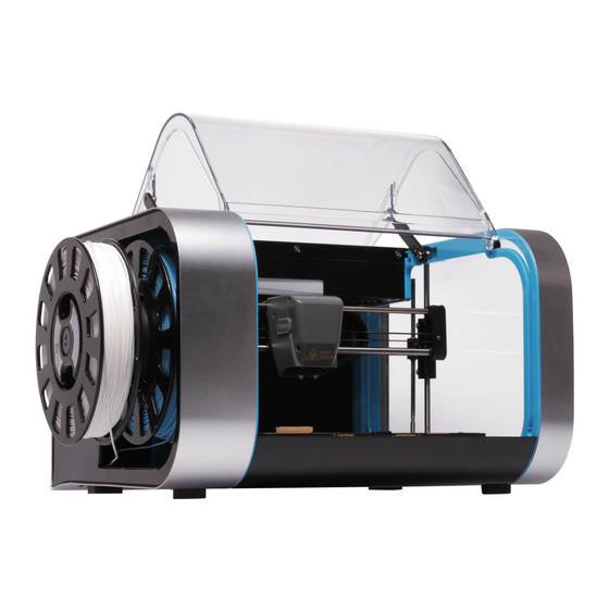
Page 23: At A Glance
2.0 Overview 2.5 At A Glance This section highlights all the major features of Robox®. Print Head X Axis Belt X Carriage Tip Wipe Blade X Axis Rails Reel Hub Cover Print Bed Door Interlock Latch Y Axis Rail Enclosure Door... - Page 24 Robox® SmartReel™ • Although there is a microSD card accessible from the back of Robox®, this cannot be read by any other machine and is only for use as internal flash storage - access is provided only for diagnostic/repair purposes.
-
Page 25: Getting Started
Getting Started... -
Page 26: Package Contents
3.0 Getting Started 3.1 Package Contents Check your product package for the following items. 2m USB A-B Cable IEC C5 Power Cable Robox® USB Flash Drive Tweezers 10x Bed Wipes Set of 4 Cleanup Tools Axis Lubricant SmartReel™ Safety Guide Warranty Card •... -
Page 27: Unpacking Robox
1. Carefully cut the tape along the top of the box, being careful not to cut too deep, and open the box. 2. Remove the accessories box from the side by pulling on the plastic handle. 3. Lift Robox® from the box using the two handles in the packing trays on either side. www.cel-robox.com... - Page 28 6. Ensure that the head and bed are free to move before proceeding. You can move them both by hand to check. • We recommend that you keep hold of all of your packaging materials should you need to return any parts to us. www.cel-robox.com...
-
Page 29: Software Installation
This section explains in detail how to install the AutoMaker™ software package for controlling your Robox®. The included USB card drive contains this software and an electronic version of this document, as well as some sample .stl files for you to print. - Page 30 Shortcuts to the Start Menu or Desktop. Then click Next > and wait as AutoMaker™ is installed to your hard drive. 9. Installation is complete. Tick the checkbox if you would like to read the ‘Readme’ file after clicking Finish. www.cel-robox.com...
-
Page 31: Starting Automaker
To start AutoMaker™, click the icon which has been added to your dock. It can also be found under Applications in Finder. 3.4.3 On Linux To start AutoMaker™, open a terminal window and navigate to the installation directory (default is “CEL/AutoMaker”) and type “./AutoMaker.run” to start. www.cel-robox.com... -
Page 32: Setting Up Your Robox® Account
3.0 Getting Started 3.5 Setting Up Your Robox® Account This section guides you through registering your Robox® and setting up an online account with us. When you start AutoMaker™ for the first time, the product and customer registration screen will be displayed, allowing you to register for product updates, support and warranty repairs. -
Page 33: Attaching The Usb Cable
3.0 Getting Started 3.6 Attaching the USB Cable Robox® comes supplied with a 2 metre USB Type A-Type B cable for connecting to your PC. Please connect as shown. • DO NOT connect your Robox® until you have been through the software installation steps on the previous page and started AutoMaker™. -
Page 34: Using Robox
Using Robox®... -
Page 35: Loading Filament
4.1 Loading Filament This section explains how to load your chosen 3D printing plastic filament into Robox® ready to produce your first print! It is designed to be a very simple process with most functions taking place automatically. 4.1.1 Preparing the Filament Before attempting to load filament, it is advisable to cut the end at a shallow angle using a knife or sharp scissors to produce a sharp tip as shown below. -
Page 36: Installing The Reel
4.0 Using Robox 4.1.3 Installing the Reel Finally, install the SmartReel™ into the dock, you should hear a click when it is correctly located, and it should appear as a recognised reel in AutoMaker™. Congratulations! - you’re now ready to print. -
Page 37: Unloading Filament
4.0 Using Robox 4.2 Unloading Filament This section explains how to remove a reel of filament for storage or to change to a different colour/material. This process has also been designed to be as simple as possible, and can even be undertaken mid-print! 4.2.1 Pause / Resume / Eject Button... -
Page 38: Removing The Reel
It is therefore essential to store your filament somewhere very dry when your Robox® is not in use for any extended period of time. SmartReels are packaged in an airtight sealable bag with a sachet of silicagel, which should remove any water from the bag and keep your filament dry. -
Page 39: The Headlock™ System
To remove the head, click the ‘Head Change’ button in AutoMaker™ and you will see the head move into position to allow easy access to the locking screw. Turn off your Robox® using the power switch on the back or at the wall outlet. -
Page 40: Installing A Head
‘snap’ as the head disconnects. 4.4.2 Installing a Head To install a new head into Robox®, the process is essentially the same in reverse. First, push the bottom of the head into the carriage until you hear/feel a ‘snap’... -
Page 41: Removing The Bed
4.0 Using Robox 4.5 Removing the Bed To remove the PEI bed from your Robox®, simply slide the handle on the front of the bed (highlighted in blue) to the left to release. Then lift up the front edge of the board using the finger recess (shown by the hand) and slide the bed towards you. -
Page 42: Automaker Software
AutoMaker Software... -
Page 43: User Interface
The diagram below shows the main screen elements of AutoMaker™. Side Bar Toolbar Advanced Tray Program Window Tab Bar www.cel-robox.com... -
Page 44: Print Workflow
5.0 AutoMaker Software 5.2 Print Workflow • AutoMaker™ is continually being improved - please check our website for an updated version of the user manual if you require further information. www.cel-robox.com... -
Page 45: Status Screen
Temperature Display Eject Filament Projects Tabs Display Advanced Settings Preferences Go To Settings Screen 5.3.1 Connected Printers This area of the screen displays the status of all printers which are currently attached to your PC. Ready Printing Paused Notification Error www.cel-robox.com... -
Page 46: Installed Filament
5.0 AutoMaker Software Each Robox® connected to AutoMaker™ has its own icon which displays the name and current status of the printer, as well as an indicator which shows the progress of the current print (if available). The status icons can be summarised as follows: •... -
Page 47: Projects Tabs
- Upload the selected project to your Robox® Account. Upload 5.3.5 Current Printer Status This part of the display provides an overview of the selected Robox®. It shows you what filament, bed and head is installed and also displays warning and status messages. -
Page 48: Advanced Settings
USB cable. Simply type the command in the text entry box (2) and then click Send GCode (3). A list of all GCode commands applicable to Robox® can be found in the Supplementary Information section at the back of this manual - section 8.1. -
Page 49: Advanced Settings - Smartreel™ Programming
5.0 AutoMaker Software 5.3.7 Advanced Settings - SmartReel™ Programming This page is for writing custom material parameters to a Robox® SmartReel™. Simply choose which reel to apply the settings to, choose a material from the list - custom or official, then click the Program Reel button. -
Page 50: Advanced Settings - Calibration And Maintenance
• Send GCode Manually AutoMaker™ can be used to send GCode manually to Robox® by one of two methods - SD (1) or USB (2) i.e. sending data to the onboard SD flash storage before executing, or transmitting each command one by one over the USB... - Page 51 Level X Gantry This button executes the automatic bed levelling algorithm. By probing the bed in multiple locations, Robox® is able to determine the level of the bed and independently adjust the Z motors to ensure the X gantry is parallel.
-
Page 52: Advanced Settings - Diagnostics
5.0 AutoMaker Software 5.3.10 Advanced Settings - Diagnostics This page is really only intended for diagnosing possible faults with your Robox®. It displays the serial numbers of the printer and the head which will be required when contacting CEL support. It also displays the state of all of the microswitches in the printer so that you can verify they are functioning correctly. -
Page 53: Layout Screen
You can rotate the view by clicking the right mouse button and dragging , pan around by holding the <Alt> key and dragging with the right mouse, and zoom by rolling the mouse wheel. www.cel-robox.com... -
Page 54: Arranging Items On The Bed
Add Model This is used to remove the selected model from the build plate. Remove Model This is used to duplicate the currently selected item and place it on the build plate. Duplicate www.cel-robox.com... - Page 55 This used to collect multiple objects together into one selection. When a group is selected, this button will toggle to ‘Ungroup’ . Group • AutoMaker™ is continually being improved - please check our website for an updated version of the user manual if you require further information. www.cel-robox.com...
-
Page 56: Settings Screen
Filament Settings box (1), and press Make! (5). AutoMaker™ will then begin to slice your 3D model and transfer to your Robox® ready for printing. Due to the unstable nature of printing ‘by wire’ - sending data over USB during a print, Robox®... -
Page 57: Filament Settings
Material Type This displays the material on the reel of filament which is currently installed in Robox® - 1 for the primary reel and 2 for the secondary. A whole range of different materials is available to purchase on SmartReels from www.cel-robox.com. -
Page 58: Print Settings
• Layer Height in microns (µm). • Perimeters use - which nozzle is used to print the outside surface of the object. • Infills use - which nozzle is used to print the inside fill of the object. www.cel-robox.com... - Page 59 It can be easily trimmed off after printing, but may greatly increase the success rate of prints with a small surface area at the base. This number specifies the number of loops (and therefore the width) of the brim. www.cel-robox.com...
-
Page 60: Advanced Settings - Material
This section explains the advanced page, and it’s associated functions and options. Material Name Bed Temperature Material Type Bed Temperature (1 Layer) Material Colour Nozzle Temperature Filament Diameter Nozzle Temperature (1 Layer) Filament Multiplier Ambient Temperature Feed Rate Multiplier Help Text www.cel-robox.com... - Page 61 This value is often set higher to ensure good adhesion when starting a print, however the temperature can be lower for the remainder of the print, or it may cause the object to ‘sag’ at its base. www.cel-robox.com...
- Page 62 • Help Text This box displays a brief explanation of the setting which is highlighted (changes on mouseover). www.cel-robox.com...
-
Page 63: Advanced Settings - Print Profile
- see section 5.5.9. • Advanced Cooling Settings This allows you to adjust advanced printing profile parameters relevant to cooling e.g. fan speeds and minimum time per layer - see section 5.5.10. www.cel-robox.com... -
Page 64: Advanced Settings - Extrusion
Layer Height Top and Bottom Layers Fill Density Number of Perimeters Fill Pattern Brim Width Infill Every ... Layers Help Text www.cel-robox.com... - Page 65 Chords Spiral • Infill Every n Layers This setting forces Robox® to add a solid infill layer every n layers. To disable this option, enter 0. • Top and Bottom Layers This setting specifies how many solid layers will be used to complete the top and bottom of the object.
- Page 66 The more perimeters, the thicker the part walls. • Brim Width This is explained in ‘Print Settings’ - see section 5.5.3. • Help Text This box displays a brief explanation of the setting which is highlighted (changes on mouseover). www.cel-robox.com...
-
Page 67: Advanced Settings - Nozzles
Perimeter Nozzle Selection Ejection Volume Fill Nozzle Selection Wipe Volume Support Nozzle Selection Partial Open Value Support Interface Nozzle Retract Length Fine Nozzle Settings (0.3mm) Retract/Unretract Speed Fill Nozzle Settings (0.8mm) Help Text www.cel-robox.com... - Page 68 • Partial Open Value This value can be used to specify a smaller needle movement as a ratio i.e. a value of 0.5 will cause the needle valve to only open halfway. www.cel-robox.com...
- Page 69 This value specifies the speed that the filament is ‘pulled back’ (retracted) at the end of an extrusion path and also pushed back in (unretracted) at the start of the next. • Help Text This box displays a brief explanation of the setting which is highlighted (changes on mouseover). www.cel-robox.com...
-
Page 70: Advanced Settings - Support
Setting this value to ‘0’ tells AutoMaker to determine this value automatically. • Force Support for First ... Layers This forces AutoMaker™ to generate support material for the first n layers regardless of the overhang threshold setting. www.cel-robox.com... - Page 71 Pattern Angle ( ° ) This option allows the direction of the support lines to be rotated in the XY plane. • Help Text This box displays a brief explanation of the setting which is highlighted (changes on mouseover). www.cel-robox.com...
-
Page 72: Advanced Settings - Speed
Perimeter Print Speed Top Solid Infill Speed Small Perimeter Print Speed Support Material Speed External Perimeter Speed Bridges Print Speed Infill Speed Gap Fill Print Speed Solid Infill Speed Help Text www.cel-robox.com... - Page 73 • Support Material Print Speed (mm/s) This parameter sets the speed at which support material is printed in millimetres per second. This value should be as fast as you can go without compromising the integrity of the support. www.cel-robox.com...
- Page 74 A smaller value here can guard against this. A setting of zero disables gap filling completely. • Help Text This box displays a brief explanation of the setting which is highlighted (changes on mouseover). www.cel-robox.com...
-
Page 75: Advanced Settings - Cooling
‘squishy’ small layers. Enable Automatic Cooling Enable Fan if Layer Time < Minimum Fan Speed (%) Go Slow if Layer Time < Maximum Fan Speed (%) Minimum Print Speed Bridges Fan Speed (%) Help Text Disable Fan for First ... Layers www.cel-robox.com... - Page 76 Minimum Print Speed (mm/s) This setting is a lower limit on how slowly a layer can be printed in millimetres per second. • Help Text This box displays a brief explanation of the setting which is highlighted (changes on mouseover). www.cel-robox.com...
- Page 77 5.0 AutoMaker Software www.cel-robox.com...
-
Page 78: Finishing Parts
Finishing Parts... -
Page 79: Removing Breakaway Support Material
Breakaway Support Material is produced using the same material as the desired part, and therefore Robox® only requires a single material head and one reel installed. A lattice of material is extruded at the same time as the rest of the part which is used to ‘prop up’... -
Page 80: Removing Soluble Support Material
6.0 Finishing Parts 6.2 Removing Soluble Support Material If your Robox® has a dual material head and second reel holder (RBX01-DM) then you can make use of Soluble Support Material for supporting your models. Your part is left with no visible blemishes and a smooth surface. The larger areas can be removed by hand to speed up the process, but it is designed to be a largely hands-off process. -
Page 81: Vapour Finishing
More information can be found online by searching for ‘vapour polishing’ , ‘vapour smoothing’ or ‘vapour finishing’ . • WARNING! Use extreme caution when handling solvents - refer to the label. Many can be extremely flammable and can also cause drowsiness, eye and respiratory irritation. www.cel-robox.com... -
Page 82: Calibration And Maintenance
Calibration and Maintenance... -
Page 83: Calibration
All calibration procedures are performed with AutoMaker™, and therefore your Robox® must be connected to your computer with the USB cable. They can be accessed through the Advanced Settings Tray on the Status screen. - Page 84 If there is anything coming out, then it is likely there is a hardware fault with your head, as it is unable to fully close the valves. If there is no material being extruded, you will move to the next stage of calibration. www.cel-robox.com...
- Page 85 Ensure both nozzles are clean before proceeding to the next step. Finally, AutoMaker™ will verify the calibration results by testing extrusion with the nozzles fully closed and fully open. www.cel-robox.com...
-
Page 86: Nozzle Height
• First, remove the ‘tip wipe’ blade in the front left of the bed. • Next, remove the PEI bed from Robox® by following the on-screen instructions. • The nozzles are clean with no lumps of filament or degraded material •... - Page 87 7.0 Calibration and Maintenance Once this measurement is complete, place the piece of paper under the left-hand nozzle (0.3mm/fine) and click Next. Robox® will then move the head down to grip the paper against the aluminium bed. Using the on-screen arrows you can adjust the height of the head. You are looking to find the lowest position where the paper is able to slide freely beneath the nozzle without touching.
-
Page 88: And Y Offset
There are a number of things you need to check before starting the calibration sequence: • You have a Robox® SmartReel™ installed in the material dock • You have already completed the nozzle opening and nozzle height calibrations as described in sections 7.1.1 and 7.1.2. - Page 89 (fill and fine) in the X and Y axes. There are diagrams on the right which show the points you are looking for. Then choose the appropriate number and letter for the profiles with the best alignment and click Next to continue. www.cel-robox.com...
- Page 90 Perfect Alignment If you are still seeing an alignment error, click the Retry Calibration button in the bottom left to try again. If you are happy with the result, click Next to complete the calibration and program the head. www.cel-robox.com...
-
Page 91: Maintenance
7.0 Calibration and Maintenance 7.2 Maintenance In order to keep your Robox® in good working condition, as small amount of maintenance is occasionally required. There are a number of routines in AutoMaker™ that guide you through the process. • AutoMaker™ is continually being improved - please check our website for an updated version of the user manual if you require further information. -
Page 92: Eject Stuck Material
This function is purely for testing the operation of the motors and motion axes. It is provided predominantly for diagnostic purposes, and should not be required during normal operation of Robox®. It simply drives all axes over their full range of movement a number of times at varying speeds to check functionality. You may be asked to perform this test by one of our support team. -
Page 93: Build Chamber
- a gentle shake should clear it out. To replace the cover, ensure all clips on the sides of the front tray cover are aligned with their mating features, and then push towards the back of Robox® to ‘snap’ into place. -
Page 94: Lubrication
This must be performed at regular intervals (approximately 200 hours of printing). There is a bottle of axis lubricant included in the accessories box which shipped with your Robox® - if this is not available, a light mineral oil would be suitable e.g. sewing machine oil. -
Page 95: Troubleshooting
7.0 Calibration and Maintenance 7.3 Troubleshooting This section of the user manual is intended to help you diagnose and fix a wide range of issues you could be experiencing with your Robox®. Problem / Symptoms Solution(s) Robox® will ‘play dead’ unless the AutoMaker™... - Page 96 3. Your printhead could be blocked. Try printing. running the purge procedure to clean out any degraded plastic that may have accumulated in the melt chamber. If these procedures have no effect, please contact CEL support. www.cel-robox.com...
- Page 97 By maintaining the ambient temperature, Robox® attempts to prevent the part shrinking, by allowing the whole object to cool evenly at the end of the print. Therefore when printing materials with a high shrink rate, it is essential that the door remains closed during printing.
- Page 98 The normal cause Software - I can’t find the print is that your filament is not installed. Please see the troubleshooting section “Hardware button! - I’m having trouble loading a new reel of filament”. www.cel-robox.com...
- Page 99 7.0 Calibration and Maintenance www.cel-robox.com...
-
Page 100: Supplementary Information
Supplementary Information... -
Page 101: Gcode Commands
Use absolute coordinates on X/Y/Z axes (default) This command causes Robox® to interpret all moves as ‘absolute’ , i.e. move to the location specified. e.g. G1 X100 Y100 will move to the fixed location 100,100. This is the default behaviour of the firmware. - Page 102 E and D, this is 1mm³ and for B this is the equivalent to the angle at full open. Show Z delta M113 This command displays the difference in height between the last two Z height probes. Show firmware version M115 Displays the firmware version which is installed on the Robox®. www.cel-robox.com...
- Page 103 M119 Extruder 2 Index Wheel. This is provided for diagnostic purposes and shows the state of all switches on Robox®. e.g. M119 X:1 Y:0 Z:0 Z+:0 E:1 D:1 B:0 Eindex:0 Dindex:1 - 1 = Switch Closed, 0 = Switch Open Load filament [E D] E = Extruder 1, D = Extruder 2.
- Page 104 This command defines the difference between how far filament has been told to travel, and how M909 far it travels in order to trigger a filament slip error. i.e. if this value is set to 2mm, and the filament is told to travel 10mm, a error will be triggered if it moves <8mm. www.cel-robox.com...
-
Page 105: Frequently Asked Questions
• What is the build volume ofRobox®? Robox® has a build area of 210x150x100mm – or a volume of 3.15 litres. Prints taller than 100mm can be scaled or we are adding functionality to AutoMaker™ which will automatically cut your part into sections for reassembly after the printing. - Page 106 8.0 Supplementary Information poor print results but damage Robox® - we can’t take responsibility for poor quality filament causing damage to the product. • Where can I find mechanical, chemical and safety specifications (MSDS) for the print materials? These will be available alongside each Robox material on our website –...
-
Page 107: Software
Ubuntu Linux (12.04+). For more information, see section 2.2. • What kind of files does Robox accept? Can I only use your library? AutoMaker™ software will currently accept the industry standard .stl and .obj format 3D models. These can be exported by most 3D design packages available including SolidWorks, Creo/ProEngineer, NX, OpenSCAD, TinkerCAD, 123d Design etc. -
Page 108: Printing
If I put two items on the bed, is it possible to print one by one rather than both together? It is possible to print one at a time, but because Robox builds vertically, a large exclusion zone is required around object 1 to prevent the head bashing into object 2 –... -
Page 109: Glossary Of Terms
A mathematical representation of the three-dimensional surface of an object (in the case of Robox®) constructed using 3D Model triangles, also known as a mesh. There are many file formats for this, with Robox®... - Page 110 - like the brim of a hat. See section 5.5.3. This is the enclosed area of Robox® where parts are produced, Build Chamber and is designed to maintain the ambient temperature and prevent draughts from affecting the quality of your print.
- Page 111 7.1. This refers to a moving assembly which is constrained to one axis - Robox® has 3 - the Z carriage which holds the X motor and Carriage rails, the X carriage that holds the print head, and the bed could be described as the Y carriage.
- Page 112 This is the computer program which runs on the hardware itself Firmware and is stored in flash memory on the mainboard. This refers to the storage available on Robox® to store GCode print instructions during printing. It also maintains a history of previous prints, allowing them to be reprinted without Flash Storage reslicing.
- Page 113 This describes the rate of extrusion from the nozzle - normally Flow Rate measured in mm³/s. This is the amount of flat area Robox® occupies when stood on Footprint a surface - 370x340mm. This describes the assembly which includes the Z carriages, Gantry X rails and X carriage.
- Page 114 This refers to the process of ensuring the nozzle is always the same distance from the print bed to ensure accurate extrusion, good base surface finish and adhesion. Robox® performs the Levelling operation automatically in both dimensions, by adjusting the level of the gantry and continually adjusting its height as the bed moves back and forth.
- Page 115 Ooze for using a ‘retract’ , where the filament is pulled back to ‘suck’ molten material away from the tip of the nozzle. Robox® uses a needle valve system to stop the extrusion as required at the tip of the nozzle, resulting in minimal ooze.
- Page 116 Polyvinyl Alcohol - A water-soluble filament used as 3D printing PVA/PVOH material, often for dissolvable support. See section 6.2.1. This refers to the twin nozzle system used by Robox® for reducing overall print times. By using a fine and fill nozzle, the QuickFill™...
- Page 117 8.0 Supplementary Information A Robox® filament definition file - contains material properties .ROBOXFILAMENT for a particular filament e.g. melt temperature. A Robox® head definition file - describes a particular head type .ROBOXHEAD and associated default parameters. .ROBOXPROFILE A Robox® print profile - contains slicing parameters Repository (Typically) an online store of 3D models for printing.
- Page 118 DC Motors which operate only in discrete increments of Stepper Motor rotation (steps). Robox® uses motors with a step angle of 1.8°, meaning there are 200 discrete steps per rotation. Short for Stereo Lithographic, the most common file format of 3D models for 3D printing.
- Page 119 PP, HDPE and ABS. The Warp enclosed build chamber of Robox® is designed to help reduce these effects, by causing the part to cool down uniformly at the end of the print and reducing draughts.
- Page 120 This is the axis which controls the motion of the gantry up and Z Axis down along the Z rail, driven by leadscrew. These are the plastic housings which hold the X rails Z Carriage perpendicular to the Z axis and form the two sides of the gantry. www.cel-robox.com...
-
Page 121: Contact Us
Please send all general feedback on Robox® to: feedback@cel-robox.com Distributor Contact Details If you purchased your Robox® from an authorised CEL reseller - please find their contact details below: Please direct all support and sales enquiries here in the first instance. - Page 122 RBX01-ACC-UM © 2014 CEL Technology Ltd. All rights reserved.
Need help?
Do you have a question about the RBX01 and is the answer not in the manual?
Questions and answers