
Related Manuals for Elmo GOLD-MAESTRO01

Summary of Contents for Elmo GOLD-MAESTRO01
- Page 1 Gold Maestro Network Motion Controller Installation Guide October 2012 (Ver. 1.300) www.elmomc.com...
-
Page 2: Revision History
This guide is delivered subject to the following conditions and restrictions: • This guide contains proprietary information belonging to Elmo Motion Control Ltd. Such information is supplied solely for the purpose of assisting users of the Gold Maestro servo drive in its installation. -
Page 3: North America
Germany Tel: +49 (0) 7721-944 7120 • Fax: +49 (0) 7721-944 7130 • info-de@elmomc.com China Elmo Motion Control Technology (Shanghai) Co. Ltd. Room 1414, Huawen Plaza, No. 999 Zhongshan West Road, Shanghai (200051) China Tel: +86-21-32516651 • Fax: +86-21-32516652 •... -
Page 4: Table Of Contents
Gold Maestro Installation Guide MAN-GOLD-MAESTRO-IG (Ver. 1.300) Table of Contents Chapter 1: Safety Information ..................6 1.1. Cautions ........................6 1.2. Directives and Standards ....................7 1.3. Warranty Information ....................7 Chapter 2: Product Description ..................8 2.1. Description .........................8 2.2. Specifications ......................9 2.2.1. - Page 5 Gold Maestro Installation Guide Table of Contents MAN-GOLD-MAESTRO-IG (Ver. 1.300) 4.1. Gold Maestro Dimensions ..................29 4.2. General Specifications ..................... 29 4.3. Environmental Conditions ..................29 4.4. Power Supply ......................30 4.5. Communications ...................... 30 4.6. Compliance with Standards ..................31...
-
Page 6: Chapter 1: Safety Information
Gold Maestro Installation Guide MAN-GOLD-MAESTRO-IG (Ver. 1.300) Chapter 1: Safety I nform ation In order to achieve the optimum, safe operation of the Gold Maestro Multi-Axis Controller, it is imperative that you implement the safety procedures included in this installation guide. This information is provided to protect you and to keep your work area safe when operating the Gold Maestro and accompanying equipment. -
Page 7: Directives And Standards
Low Voltage Directive 73/23/EEC The Gold Maestro has been developed, produced, tested and documented in accordance with the relevant standards. Elmo Motion Control is not responsible for any deviation from the configuration and installation described in this documentation. Furthermore, Elmo is not responsible for the performance of new measurements or ensuring that regulatory requirements are met. -
Page 8: Chapter 2: Product Description
2.1. Description The Gold Maestro is Elmo’s network motion controller. It works in a network based system in conjunction with Elmo’s intelligent servo drives to provide a total multi-axis motion control system solution. -
Page 9: Specifications
Gold Maestro Installation Guide Product Description MAN-GOLD-MAESTRO-IG (Ver. 1.300) 2.2. Specifications 2.2.1. Gold Maestro Hardware • Hardware: Stand-alone • Power Supply: Single DC supply, with two product options available: 13 VDC to 96 VDC 20 VDC to 196 VDC ... -
Page 10: Gold Maestro Software
Motion Programming and Debugging Native C Programming, running on the target CPU. Compiling and debugging via the Eclipse IDE using GCC under Cygwin IEC 61131-3 with PLCopen Motion Library extension, using Elmo IDE. The following languages are supported: •... -
Page 11: Man-Gold-Maestro-Ig (Ver. 1.300
This is a unique feature, required for the generation of position-based events in 3D scanning systems. The Gold Maestro system, with Elmo’s intelligent Gold servo drives, can support single axis and spatial enhanced position-based compare functions, resulting in trigger output signals accurate to 1 encoder count along the trajectory path. -
Page 12: Communication Options
This manual is part of a documentation set that can be used to set up and program the motion of any machine whose motors are controlled by Elmo’s SimplIQ or Gold Line servo drives. When used in conjunction with the Gold Maestro Software Manual it describes everything needed to get the Gold Maestro up and running. -
Page 13: Chapter 3: Installation
Gold Maestro Installation Guide MAN-GOLD-MAESTRO-IG (Ver. 1.300) Chapter 3: I nstallation 3.1. Before You Begin 3.1.1. Site Requirements For safe operation of the Gold Maestro make sure it is installed in an appropriate environment. Feature Value Ambient operating temperature 0 °C to 40 °C (32 °F to 104 °F) Maximum non-condensing humidity Operating area atmosphere No flammable gases or vapors permitted in area... -
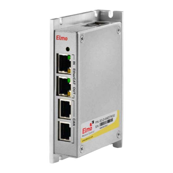
Page 14: Connectors
4. The part number at the top gives the type designation as follows: GOLD-MAESTRO01: 13 to 96 VDC power supply GOLD-MAESTRO02: 20 to 196 VDC power supply 5. Verify that the Gold Maestro type is the one that you ordered. -
Page 15: Pinouts
Gold Maestro Installation Guide Installation MAN-GOLD-MAESTRO-IG (Ver. 1.300) Pins Type Function RJ-45 EtherCAT Out RJ-45 CAN1 RJ-45 CAN2 Bottom Connectors RJ-45 Ethernet Table 1: Connector Types 3.3.2. Pinouts 3.3.2.1. Power Connector See Section 3.5.2 for full details. Function Protective Earth Power Return Positive Power Input Connector Location... -
Page 16: Ethercat In Connector
Gold Maestro Installation Guide Installation MAN-GOLD-MAESTRO-IG (Ver. 1.300) 3.3.2.2. EtherCAT In Connector See Section 3.5.6 for full details. Signal Function EtherCAT_IN/Ethernet_TX+ EtherCAT in/Ethernet transmit + EtherCAT_IN/Ethernet_TX- EtherCAT in/Ethernet transmit - EtherCAT_IN/Ethernet_RX+ EtherCAT in/Ethernet receive + EtherCAT_IN/Ethernet_RX- EtherCAT in/Ethernet receive - 7, 8 Connector Location Cable Connector... -
Page 17: Canopen Connectors
Gold Maestro Installation Guide Installation MAN-GOLD-MAESTRO-IG (Ver. 1.300) 3.3.2.4. CANopen Connectors See Section 3.5.5 for full details. Signal Function CAN_H CAN_H bus line (dominant high) CAN_L CAN_L bus line (dominant low) CAN_COMRET CAN Communication Return — CAN_SHLD Shield, connected to the RJ-45 plug cover CAN_COMRET CAN Communication Return —... -
Page 18: Usb 2.0 Connector
Gold Maestro Installation Guide Installation MAN-GOLD-MAESTRO-IG (Ver. 1.300) Table 6: Ethernet Pin Assignments 3.3.2.6. USB 2.0 Connector See Section 3.5.4 for full details. Signal Function USB VBUS USB VBUS from host USBD- USB _N line USBD+ USB _P line USB COMRET USB communication return Connector Location Cable Connector... -
Page 19: Man-Gold-Maestro-Ig (Ver. 1.300
Gold Maestro Installation Guide Installation MAN-GOLD-MAESTRO-IG (Ver. 1.300) Figure 2: Wall Mounting the Gold Maestro www.elmomc.com... -
Page 20: Surface Mount
Gold Maestro Installation Guide Installation MAN-GOLD-MAESTRO-IG (Ver. 1.300) 3.4.2. Surface Mount Use four M4 round head screws, one through each opening in the heat sink to connect the Gold Maestro to a surface. Figure 3: Surface Mounting the Gold Maestro 3.4.3. -
Page 21: Connecting The Cables
Gold Maestro Installation Guide Installation MAN-GOLD-MAESTRO-IG (Ver. 1.300) 3.5. Connecting the Cables 3.5.1. Wiring the Gold Maestro Once the Gold Maestro is mounted, you are ready to wire the device. Proper wiring, grounding and shielding are essential for ensuring safe, immune and optimal performance of the Gold Maestro. -
Page 22: Connecting The Dc Power Supply
Gold Maestro Installation Guide Installation MAN-GOLD-MAESTRO-IG (Ver. 1.300) Type Port Connector Location RJ-45 EtherCAT In/ EtherCAT Out RJ-45 CAN x 2 Table 9: Connectors on the Front of the Gold Maestro Type Port Connector Location RJ-45 Ethernet Table 10: Connectors on the Top of the Gold Maestro 3.5.2. -
Page 23: Ethernet
Gold Maestro Installation Guide Installation MAN-GOLD-MAESTRO-IG (Ver. 1.300) Figure 5: Power Supply Connection Diagram 3.5.3. Ethernet Note: When connecting the Ethernet communication cable use a shielded CAT5e Ethernet cable. The Gold Maestro connects to a PC either directly or through a hub, switch or router. Use a standard or cross CAT5e Ethernet cable. -
Page 24: Usb 2.0 Communication
Gold Maestro Installation Guide Installation MAN-GOLD-MAESTRO-IG (Ver. 1.300) 3.5.4. USB 2.0 Communication The USB Network consists of Host controller and multiple devices. The GMAS is a USB Device. Notes for connecting the USB communication cable: Connect the shield to the ground of the host (PC). Usually, this connection is soldered internally inside the connector at the PC end. -
Page 25: Canopen Communication
Gold Maestro Installation Guide Installation MAN-GOLD-MAESTRO-IG (Ver. 1.300) 3.5.5. CANopen Communication Notes for connecting the CANopen communication cable: Use 26 or 28 AWG twisted pair shielded cables. For best results, the shield should have aluminum foil and be covered by copper braid with a drain wire (CAT5e FTP applicable). Connect the shield to the ground of the host (PC). -
Page 26: Man-Gold-Maestro-Ig (Ver. 1.300
Gold Maestro Installation Guide Installation MAN-GOLD-MAESTRO-IG (Ver. 1.300) Signal Function Pin Position CAN_H CAN_H bus line (dominant high) CAN_L CAN_L bus line (dominant low) CAN_COMRET CAN Communication Return 4, 5 — CAN_SHLD Shield, connected to the RJ plug cover CAN_COMRET CAN Communication Return —... -
Page 27: Ethercat Communication
Gold Maestro Installation Guide Installation MAN-GOLD-MAESTRO-IG (Ver. 1.300) 3.5.6. EtherCAT Communication The Gold Maestro is the master of the EtherCAT network and must always be the first device in the line. The EtherCAT Out port of the Gold Maestro should be connected to the EtherCAT In port of the next device down the line. -
Page 28: Powering Up
Setting up the drives and motors is described in the Installation Guide for each servo drive and in the Elmo Application Studio User Guide. Advanced features are described in the SimplIQ Software Manual, Interlude API User Guide, SimplIQ Command Reference and CANopen Implementation Guide. -
Page 29: Chapter 4: Technical Specifications
Gold Maestro Installation Guide MAN-GOLD-MAESTRO-IG (Ver. 1.300) Chapter 4: Technical Specifications 4.1. Gold Maestro Dimensions All measurements are in mm. 4.2. General Specifications Feature Details Weight 250 g (8.75 ounces) Dimensions 115 mm x 75 mm x 25.4 mm (4.53" x 2.95" x 1") Mounting Method (with adapter) Wall Mount (“Bookshelf”) 4.3. -
Page 30: Power Supply
Gold Maestro Installation Guide Technical Specifications MAN-GOLD-MAESTRO-IG (Ver. 1.300) 4.4. Power Supply Feature Details DC source only Auxiliary power supply Auxiliary supply input voltage 13 V to 96 V or 20 V to 196 V depending on the model Auxiliary supply input power 4.5 W 4.5. -
Page 31: Compliance With Standards
Gold Maestro Installation Guide Technical Specifications MAN-GOLD-MAESTRO-IG (Ver. 1.300) 4.6. Compliance with Standards Specification Details Quality Assurance ISO 9001:2008 Quality Management Design Approved IEC/EN 61800-5-1, Safety Printed wiring for electronic equipment (clearance, creepage, spacing, conductors sizing, etc.) MIL-HDBK- 217F Reliability prediction of electronic equipment (rating, de-rating, stress, etc.) •... - Page 32 In compliance with 2002/96/EC Waste Electrical and Electronic Equipment regulations (WEEE) Note: Out-of-service Elmo drives should be sent to the nearest Elmo sales office. In compliance with 2002/95/EC Restrictions on Application of Hazardous (effective July 2006) Substances in Electric and Electronic Equipment (RoHS) www.elmomc.com...
Need help?
Do you have a question about the GOLD-MAESTRO01 and is the answer not in the manual?
Questions and answers