Table of Contents
Advertisement
Quick Links
AUTOMATIC TECHNOLOGY AUSTRALIA PTY LTD
TM
Pro Series 1100
COMMERCIAL
OVERHEAD DOOR OPENER
NOTE: A Photo Electric Beam
Sensor must be fitted with this
opener. Failure to comply will
void the warranty and may
cause serious personal injury
and/or property damage.
WARNING
OWNERS COPY
It is vital for the safety of persons to follow all
instructions. Failure to comply with the installation
instructions and the safety warnings may result in
serious personal injury and/or property and remote
Installation Instructions
control opener damage.
Please save these instructions for future reference.
Advertisement
Table of Contents

Summary of Contents for Axess Pro Series 1100
-
Page 1: Installation Instructions
AUTOMATIC TECHNOLOGY AUSTRALIA PTY LTD Pro Series 1100 COMMERCIAL OVERHEAD DOOR OPENER NOTE: A Photo Electric Beam Sensor must be fitted with this opener. Failure to comply will void the warranty and may cause serious personal injury and/or property damage. -
Page 2: Table Of Contents
CONTENTS PAGE CONTENTS IMPORTANT SAFETY WARNINGS FEATURES PRODUCT DESCRIPTION BEFORE DRIVE UNIT INSTALLATION DRIVE UNIT INSTALLATION CONTROL BOARD LAYOUT WIRING DIAGRAM - THREE PHASE SETTING TRAVEL LIMITS SETTING PEDESTRIAN POSITION CHANGING ACCELERATE/DECELERATE SPEED DESCRIPTION OF STANDARD OPERATION MENU STRUCTURE CONTROL BOARD ADJUSTMENTS MENU 3 AUTO-CLOSE TIMES MENU 4 LOCK TIMES MENU 5 LIGHT TIMES... - Page 3 PLEASE READ THESE IMPORTANT SAFETY RULES Warning - It is vital for the safety of persons to follow all instructions. Failure to comply with the following Safety Rules may result in serious personal injury and/or property damage. For SAFETY protection a Photo Electric Beam MUST The opener is not showerproof - it should not be be fitted with this opener.
-
Page 4: Features
FEATURES Thank you for purchasing the ATA Axess HOPPING CODE TRANSMITTERS EXTENSIVE OPERATING MODES Automatic Opener. This opener is The opener incorporates SecuraCode V I A C O N T R O L I N P U T S A N D ®... -
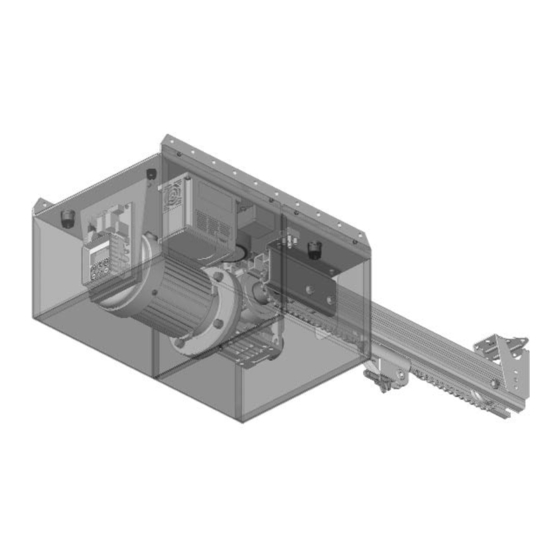
Page 5: Product Description
PE Beams etc. BEFORE DRIVE UNIT INSTALLATION The ATA Axess Pro Series 1100 Panel Door Opener is designed 2. The mounting must be solid construction (concrete, brick or to operate most commercial heavy duty and heavy residential steel. -
Page 6: Drive Unit Installation
DRIVE UNIT INSTALLATION DRIVE UNIT PRE-ASSEMBLY CENTRE OF DOOR FIG. 3 The drive unit and track assembly are supplied as two separate parts. The drive sprocket is part of track assembly. 1. To connect track to drive unit remove front cover. 2. -
Page 7: Control Board Layout
CONTROL BOARD LAYOUT 1 & 2. 24VDC output for powering accessories 3A(max) STP Input Jumper (remove when 10 is used) Lock relay output N/C contact Console Exit Button Lock relay output COM contact Console Previous Button Lock relay output N/O contact Console Down/Close Button Drive unit connections Console Up/Open Button... -
Page 8: Wiring Diagram Three Phase
WIRING DIAGRAM THREE PHASE... -
Page 9: Setting Travel Limits
SETTING TRAVEL LIMITS CAUTION: CABLES WHICH HAVE A GREEN/YELLOW COLOURED INSULATION ARE FOR EARTHING PURPOSES ONLY. NEVER USE THESE CABLES FOR ANY OTHER PURPOSE. This section shows how to set the travel limits. The procedure can STARTUP SCREEN FIG. 8 be partly completed using a transmitter. - Page 10 SETTING TRAVEL LIMITS STEP 4. SETTING CLOSE TRAVEL LIMIT FIG. 13 To CLS Limit, 1. Press CLOSE to move door to the desired CLOSE LIMIT. / / \ \ \ \ / / (Or Press button 4 on transmitter) (Fig. 13). Adjust, 2.
-
Page 11: Setting Pedestrian Position
SETTING PEDESTRIAN POSITION FOR OPENERS WITHOUT AN ENCODER FITTED. FIG. 16 MENU 10.2 Set Pedestrian Note: Before setting the pedestrian access position the door must be in the fully closed position. As with the Setting Travel Limit procedure, a transmitter can be used to complete the pedestrian position setting procedure. -
Page 12: Description Of Standard Operation
DESCRIPTION OF STANDARD OPERATION This section describes the standard operation of the control board PEDESTRIAN ACCESS (PED) FUNCTION with the factory set default values. (Activated by PED terminal with N/O switch or by transmitter button with PED Function assigned). MOTOR CONTROL. The pedestrian access operation partly opens the door allow The controller drives the motor in the appropriate direction as pedestrian access but prevent vehicle access. -
Page 13: Menu Structure
MENU STRUCTURE... -
Page 14: Control Board Adjustments
CONTROL BOARD ADJUSTMENTS The opener’s standard operation can be altered by editing various parameters. This section describes the parameters and the effect they have. Use the VIEWING AND EDITING PARAMETER PROCEDURE on Page 17 to make changes. MENU 2 - OBSTRUCTION MARGINS MARGINS The obstruction margins are used to alter the sensitivity of the allowable variation between the “normal”... -
Page 15: Menu 4 Lock Times
CONTROL BOARD ADJUSTMENTS MENU 4 - LOCK TIMES Lock output can be programmed for both hold and pulse door motor starting. The operation of the lock can be programmed operation and can also be programmed to activate prior to the to behave differently on open cycle to that on close cycles. -
Page 16: Menu 7 Operating Modes
CONTROL BOARD ADJUSTMENTS MENU 7 - OPERATING MODES P.E INPUT RESPONSE MODE ACTIVITY REPORT ID The P.E input can be configured to respond in one of three modes. This parameter sets the ID of the controller that is sent with the OPEN AND CLOSE CYCLES STOP activity report. - Page 17 VIEWING AND EDITING PARAMETER This section illustrates how to locate, view and adjust parameters. LOCATING PARAMETERS RELOAD DEFAULT SETTING Refer to MENU STRUCTURE on Page 13 or the preceding 1. Press NEXT/PREV buttons to display LOAD DEFAULT section for CONTROL BOARD ADJUSTMENTS. Locate the screen.
-
Page 18: Coding Transmitters
CODING TRANSMITTER Up to 511 transmitters can be stored within the openers memory. FIG. 22 Each transmitter can be allocated an alpha-numeric ID label up to ID / SN display indicator eleven (11) characters in length and each button can be assigned to I.D Label / Serial Number Store Number one of several control functions. -
Page 19: Transmitter Edit Procedure
TRANSMITTER EDIT PROCEDURE EDITING TRANSMITTER SETTINGS FIG. 28 A B SMITH I I D D STEP 1. DISPLAY TRANSMITTER RECORD OSC PED LGT VAC Using one of the methods below, display the required transmitters details. PRESS STEP1. NAVIGATING TO “Edit Transmitter” MENU 1. -
Page 20: Transmitter List Management
TRANSMITTER MANAGEMENT The opener provides a transmitter listing facility which enables the Method 2 - Use Transmitter to go Direct to List user to find a transmitter location within memory. Once located a STEP 1 ACCESSING THE LIST MENU stored transmitter can be replaced, deleted, edited, copied or, if the 1. -
Page 21: Code Operation (Location Empty)
TRANSMITTERS MANAGEMENT Once the list is displayed it can be sorted by Store number, ID FIG. 41 B B SMITH I I D D Label or Serial Number. Use NEXT or PREV button to select sort- OSC PED LGT VAC ing method. -
Page 22: Remote Code Set Procedure
REMOTE CODE SET PROCEDURE If a transmitter is already coded into the opener, additional FIG. 46 transmitters can be coded without being in direct contact with the opener’s control panel. PRESS NOTE: Only the function of the existing transmitter button can be Existing assigned to new transmitter. -
Page 23: Menu 8.1 Test Inputs
DIAGNOSTIC TOOLS The controller provides several diagnostic tools from within the FIG. 49 MENU 8 diagnostics menu (menu 8) this section details the function of Diagnostics each tool and its use. NAVIGATING TO DIAGNOSTICS MENU 1. Press PREV to navigate Menu 8 (Fig. 49). 2. -
Page 24: Menu 8.5 Service Counter
DIAGNOSTIC TOOLS MENU 8.5 SERVICE COUNTER FIG. 55 Service Counter The opener provides a periodic service counter which can be set to (CYCLES) 60000 expire after a number of drive cycles.When expired, the opener will beep at the beginning of each drive cycle and a message will be displayed on the MAIN SCREEN (Fig. -
Page 25: Accessories Installation
ACCESSORIES INSTALLATION This opener does not feature an inherent obstruction FIG. 58 detection (reversing) system. For safety a PE Beam MUST be fitted. FITTING PHOTO ELECTRIC BEAM Locate the Photo Electric (P.E.) Beam in a strategic location in the gateway. ATA recommend that the sensor is placed 150mm above the floor level and as close as possible to the door opening. -
Page 26: Trouble Shooting Guide
TROUBLE SHOOTING GUIDE POSSIBLE CAUSE POSSIBLE CAUSE REMEDY Door will not operate. Mains power not switched on. Switch on mains power. Door is obstructed. Remove obstruction. Door is locked or motor jammed. Unlock door or remove jam. Door tracks/hardware damaged. Door requires service/repair by qualified technician. -
Page 27: Parts List
PARTS LIST WHEN ORDERING SPARE PARTS PLEASE QUOTE THE ORDER CODE NUMBER TO YOUR INSTALLER/DISTRIBUTOR... -
Page 28: Warranty And Exclusion Of Liability
Trade Practices Act 1974 (Cth). 2. Subject to all of the matters set out below, Automatic Technology Australia Pty Ltd ("ATA") warrants: (a) the Axess Pro Series Opener for twelve (12) months, (b) all components and accessories for twelve (12) months, from the date of purchase (specified in the sales docket receipt) as free of any defects in material and workmanship.
Need help?
Do you have a question about the Pro Series 1100 and is the answer not in the manual?
Questions and answers