Advertisement
Quick Links
Advertisement

Summary of Contents for x-erfit 590 RB
- Page 1 USER’S MANUAL 590 RB cycle BUILT FOR HEALTH...
-
Page 2: Safety Instructions
SAFETY INSTRUCTIONS • When setting up the exerciser, please make sure that the exerciser is standing in a stable way and that any possible unevenness of the To ensure the best safety of the exerciser, regularly floor is evened out. check it on damages and worn parts. -
Page 3: Important Notes
IMPORTANT NOTES • Assemble the exerciser as per assembly instructions and be sure to only use the structural parts provided with the exerciser and designed for it. Prior to the assembly, make sure the content of the delivery is complete by referring to the parts list of the assembly and operating instructions. -
Page 4: Explosive Drawing
EXPLOSIVE DRAWING... - Page 5 Picture of spare parts D22xD8.5 M8x20L M8x75L M8*40L D15.4xD8.2 M8x55L M8x90L D16x1.2T M8x15L...
-
Page 6: Specifications
Part List part description specifications q'ty Main frame Front stabilizer D60x1.5Tx390L Rear stabilizer Seat tube set Handlebar set Seat adjustable tube set Seat support tube set computer UM-6636L2-7 Foot cap (round) D60x71x101L Handlebar post set Spring washer D15.4xD8.2x2T Domed nut M8x1.25x15L,8.8 Inner Allen bolt M8x1.25x20L,8.8... - Page 7 Middle hand pulse cable 550L Upper hand pulse cable 700L Lower hand pulse cable Hand pulse cable 700L,rolling cable Adaptor Output:6V Crank bearing welding set Bushing D20*D14*11.5T Fixing plate for idle wheel 156*62.2*5T Idle wheel D23.8xD38x24 Square neck bolt M8x1.25x75L,8.8 Square neck bolt M8x1.25x55L,8.8 Plastic cover...
- Page 8 ASSEMBLY STEP 1 M8x20L D15.4 FIG.1 Assemble rear stabilizer (3) to main frame (1) use spring washer (11), inner Allen bolt (13) &curved washer(31).
- Page 9 STEP 2 M8x90L D15.4 M8x15L M8x75L M8x15L D15.4 FIG.2 Assemble front stabilizer(2) to the main frame use spring washer(11),inner domed nut(12),curved washer(31)&square neck bolt(35).And then assemble the seat adjustable tube set(6) to the main frame use spring washer(11),inner domed nut(12),curved washer(31)& square neck bolt(30).
- Page 10 STEP 3 M8*40L FIG.3 Assemble the seat (18) to the seat support tube set (7) use inner Allen bolt (15) &nylon nut (66). Then assemble the sliding beam set (60) to seat support tube set (7) use ball pulling knob (40).
- Page 11 STEP 4 M8x55L D15.4 M8x15L 60 56 47 47 FIG.4 Assemble two middle hand pulse cable (47) together. Then assemble sliding beam set (60) to the main frame(1) use spring washer(11),inner domed nut(12),square neck bolt (55) & nylon nut (66).
- Page 12 STEP 5 M8x20L D15.4 FIG.5 Assemble handlebar set (5) to seat tube set (4) use spring washer (11), inner Allen bolt (13), & nylon nut (66) ,and assemble seat tube set (4) to seat support tube set (7).
- Page 13 STEP 6 M8*40L M8x20L D15.4 FIG.6 Assemble back pad (25) to seat tube set (4) use inner Allen bolt (15) & nylon nut (66). Connect upper computer cable (41) and motor cable (42) also connects middle hand pulse cable (46) & upper hand pulse cable (47) together. Then assemble handlebar post to main frame (1) use spring washer (11), inner Allen bolt (13) &curved washer (31).
- Page 14 STEP 7 75 6 FIG.7 Assemble the computer(8) and pedals (20L&R). A, connect upper hand pulse cable (47) and lower hand pulse cable (48) together. B, assemble the front cover (75) to seat support tube (6).C, plug hand pulse cable (49).
- Page 15 STEP 8 FIG.8 Plug the adaptor (50).
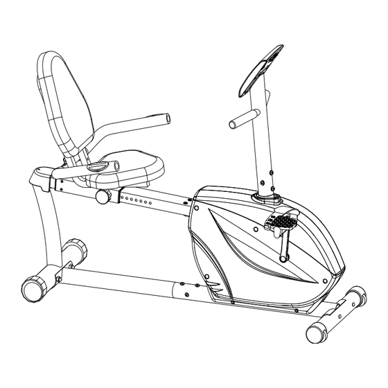
- Page 16 The handlebar and the back pad is adjustable.
- Page 17 English Manual for UM6636L2-7 24 LOAD LEVELS DISTANCE DISPLAY USER DATA RPM / SPEED DISPLAY PULSE / HRC Kilometers per hour (km/h) WATTS /CALORIES TIME: 00:00( MIN:SEC) + UP –Select / increase Function value RECOVERY Select / increase Program RESET – Reset original setting –...
- Page 18 SELECT MANUAL/PROGRAMS/ WATT CONSTANT/USER/H.R.C User can choose different control mode to start his work out. See below is main description of each control mode. EXECUTE MANUAL/PROGRAMS/ WATT CONSTANT/USER/H.R.C Execute selected control mode. PRE-SET TIME/DISTANCE/CALORIES/WATTS/HEART RATE Setting and inputting user wanted function value of above, the function value of display will count down to zero;...
- Page 19 RECOVERY When you have finished your workout, press RECOVERY. For RECOVERY to function correctly, it needs your Heart Rate input. TIME will count - from 1 minute and then your fitness level from F1 to F6 will be displayed. NOTE: during RECOVERY, no other displays will operate. F 1 ~ F6 = RECOVERY HEART RATE LEVEL SCORE CONDITION...
- Page 20 IMPORTANT INFORMATION REGARDING SERVICE In you have any problems, please contact Mylna Service. Our consultants have extensive experience and will help you with questions about products, installation, ordering spare parts or any errors and omissions. We would like you to contact us before contacting the store so we can offer you the best help. Please visit our website www.xerfit.fi - here you will find information about the products and user manuals in Finnish and English.
Need help?
Do you have a question about the 590 RB and is the answer not in the manual?
Questions and answers