Table of Contents
Advertisement
Quick Links
Heat Exchanger
Heat Exchanger
& Keel Cooled
& Keel Cooled
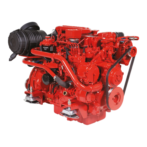
Mid Diesel Engine Range:
Mid Diesel Engine Range:
Beta 75, Beta 90 & Beta 105
Beta 75, Beta 90 & Beta 105
CALIFORNIA - Proposition 65 Warning: Diesel engine exhaust and some of its constituents are known to the state of
California to cause cancer, birth defects and other reproductive harm.
Operator's
Operator's
Maintenance
Maintenance
Manual
Manual
Advertisement
Table of Contents

Summary of Contents for Meta Marine Beta 75
- Page 1 Mid Diesel Engine Range: Mid Diesel Engine Range: Beta 75, Beta 90 & Beta 105 Beta 75, Beta 90 & Beta 105 CALIFORNIA - Proposition 65 Warning: Diesel engine exhaust and some of its constituents are known to the state of...
- Page 2 Fig 1 Typical Heat Exchanger Cooling System...
- Page 3 Engine Details Please fill in these details at moment of purchase - it really will help you! IMPORTANT! (and it will really help us specify the correct spare parts for you). Engine Type: Power: Speed: BETA WOC NO: Gearbox Type: Purchased From: Invoice No.: Date Commissioned:...
-
Page 4: Table Of Contents
Contents Engine details (to be completed now) Introduction Engine identification Initial receipt of the engine Engine storage Safety precautions Technical specifications SECTION 1: INSTALLATION GUIDELINES Engine mounting Engine alignment - drives, flanges, flexible couplings Exhausts and mounting exhausts Fuel supply and “leak off” Cooling - sea water inlet system Cooling - keel cooling system Calorifier connections (if fitted) - Page 5 OPERATION AND MAINTENANCE MANUAL FOR THE FOLLOWING BETA MARINE ENGINES BASED ON KUBOTA Beta 75, Beta 90 & Beta 105 WELCOME TO BETA MARINE Thank you for purchasing a Beta Marine Engine. We have made this manual to provide you with important information and recommendations to ensure trouble free and economical operation of the engine.
-
Page 6: Engine Identification
- We are asking you to always provide the WOC (Works Order Card number and or the engine serial number in all communications concerning your engine Beta Marine WOC Number BETA 75, BETA 90 & BETA 105 The engine serial number is shown on the rocker cover Engine Serial Number label. -
Page 7: Safety Precautions
Safety Precautions! A Keep the engine, gearbox and surrounding area ii) Fuel Supply Connections clean, including the area immediately below the Engines are supplied with 8mm compression fittings. engine. The installer must ensure that when connections are B Drives - Power Take Off Areas made, they are clean and free of leaks. -
Page 8: Technical Specifications
Technical Specifications Standard Engines Beta 75 Beta 90 Beta 105 Cylinder Bore (mm) Stroke (mm) 120.0 120.0 120.0 Displacement (cc) 3620 3769 3769 Combustion Indirect NA Direct NA Direct & Turbo 45.8 56.0 68.1 Power Output EN ISO 8665 at rev/min... - Page 9 Section 1 INSTALLATION RECOMMENDATIONS The installation details are basic guidelines to assist • Unless the engine is protected by a cover or its own installation, however due to the great diversity of marine enclosure, exposed moving or hot parts of the engine craft it is impossible to give definitive instructions.
-
Page 10: Engine Mounting
ENGINE MOUNTING To ensure vibration free operation, the engine must be Engine Mount installed and correctly aligned on substantial engine bearers, extending as far forward and aft as possible, well braced and securely fastened to form an integral part of the hull. - Page 11 ALIGNMENT To obtain accurate alignment the flexible mountings must mounted on a magnetic foot so that they are aligned be adjusted until alignment is attained, and the mountings within 0.125mm (0.005”). (Obviously the propeller shaft must be locked in position. The engine / gearbox unit has must be centered in the stern tube and running true - to be aligned with the propeller shaft in two ways.
- Page 12 FLEXIBLE OUTPUT COUPLINGS A flexible coupling is mounted on the gearbox output flange and is strongly recommended in almost every case. Flexible couplings do not resolve bad alignment, they are designed to absorb torsional vibrations from the propeller (transmitted along the propeller shaft). We normally offer two types: R&D with a flexible nylon disc and optional Clamp Coupling –...
- Page 13 EXHAUST SYSTEMS There are two main types of exhaust system: We recommend care when designing your exhaust system. The most important aspect is to ensure that water 1) Standard yacht - wet exhaust system with a water cannot enter the engine’s combustion chamber from the injection bend and waterlock silencer exhaust system (this applies to both wet and dry exhaust 2) Dry exhaust system (see page 17)
- Page 14 HIGH-RISE EXHAUST In yachts, engines are mostly installed low down and standard injection bend is too low then we can offer a often below the water line. There are several ways to high-rise injection bend that adds 15 cms to the height. avoid cooling water entering the engine.
- Page 15 WATERLOCK / SILENCER You must always fit a waterlock / silencer to stop any injection bend, being as low as reasonably possible, so water in the exhaust system back filling the engine. The that all the water can drain down into it. The waterlock water lock should always be fitted at least 30 cms away should have sufficient capacity to hold an exhaust system from the injection bend and at least 30 cms below the...
- Page 16 Beta 43 to Beta 60 25 mm / 1“ min. clips should be used at each end of raw water pipes Beta 75 to Beta 105 28 mm / 1 ” min. for security. Ensure that you use the correct grade of hose.
- Page 17 Stern Bleed with Anti-syphon Valve Beta 10 to Beta 60 - can be connected to the heat Beta 75 upwards - need a ‘T’ piece with an 1/8” BSP exchanger end cap using our ‘Stern Bleed kit’ and drilling connection fitted just after the heat exchanger as shown and tapping the end cap.
- Page 18 An engine correctly installed in Beta 10 to Beta 60 50 mm accordance with this handbook will meet the emission requirements of the RCD (Recreational Craft Directive). Beta 75 & Beta 90 60 mm Beta 105 75 mm EXHAUST BACK PRESSURE...
- Page 19 DRY EXHAUST INSTALLATION a) An engine correctly installed in accordance with this • Never use a flexible exhaust bellow as a bend, it will handbook will meet the emission requirements of the crack, always keep them straight. RCD (see back of manual). •...
-
Page 20: Fuel Supply And Leak Off
ENGINE CONNECTIONS Actual Connector: Required Pipe Size: Fuel supply and leak-off = 8 mm conex with olives 8 mm OD piping for both, a flexible section is required Seawater cooling pump = 28 mm OD Seawater pump inlet = 28 mm ID hose Exhaust water injection bend = 60 mm OD Flexible rubber exhaust pipe of correct quality = 60 mm ID FUEL SUPPLY &... - Page 21 CALORIFIER SYSTEM All Beta engines can be fitted with the calorifier Heat Exchanger Calorifier System connections to allow the coolant from the closed circuit cooling system to circulate through a calorifier tank, which in turn heats up domestic water. Calorifier connections on this range of engine are shown.
- Page 22 The Beta 75 and Beta 90 propulsion engines arranged These keel cooling tanks are normally welded into the for keel cooling have both engine supply and return ‘swim’...
- Page 23 The hot water feed enters at the top of the tank Beta 43 10.8 1.00 and the engine return comes out of the bottom. Beta 50 12.5 1.16 Beta 60 15.5 1.43 Beta 75 18.8 1.75 Beta 90 22.5 2.09 Beta 105 25.0 2.32 Ideal Keel Cooling Tank...
-
Page 24: Electrical Installation
ELECTRICAL INSTALLATIONS All our engines are supplied with 12 volt electric starting Care must be taken when pushing the two halves of as standard. We therefore supply the main components: the plug together to ensure that individual pins do not starter motor, battery charging alternator, fuel control fall out. - Page 25 100 to 120 AH 580 to 670 Over 3,000cc 2.0 - 3.0 Beta 75 to 105 150 to 180 AH 1050 to 1200 6. Battery charging alternators must be suitable for 7. Batteries must be in good condition and must hold the battery bank size.
- Page 26 BATTERY CABLES 1. Starter batteries should be as close to the engine as If the correct battery is selected but the engine will practically possible. The reason for this is to ensure not crank at sufficient speed after the inrush then that the maximum voltage from the battery is available (assuming battery cables are the correct size) the to the starter motor.
- Page 27 70mm Cable Engine Cranking Amps Cable Volt drop* Max length, both cables added together Up to Beta 38 0.00063V 12.7m Up to Beta 50 0.00063V 10.5m Up to Beta 60 0.00063V 7.5m Up to Beta 105 210 / 250 0.00063V 5.0m Beta 150 0.00063V...
-
Page 28: Section 2: Guidelines For Operation Of The Engine
Section 2 GUIDELINES FOR OPERATION OF ENGINE IMPORTANT! CHECKS PRIOR TO INITIAL USE 1. Generally, a new engine has the oil and anti-freeze removed after the works test. Fill the engine with the correct oil and antifreeze (see sections on Engine oil and Cooling). - Page 29 8. Start engine (see normal starting). Note the engine CAUTION: may have to be turned over with the starter for a few seconds before it fires. TO AVOID PERSONAL INJURY! Do not run the starter for more than 20 seconds. If •...
- Page 30 NORMAL STARTING BETA CONTROL PANELS - ABV, A, AB, B AND C DELUXE - WITH KEYSWITCH. 3. Turn to ‘START’ position and engine will motor, hold To operate the engine: with the engine out of gear, set in position until engine fires (see initial start-up section speed control lever to throttle.
- Page 31 NORMAL STARTING BETA CONTROL PANEL ABVW - KEYLESS (WITHOUT KEYSWITCH) This panel controls the engine with three water resistant 2. Press ‘START’ button and hold in position until engine push buttons instead of a keyswitch, and is less prone to fires (see initial start-up section for maximum time damage and corrosion from sea water spray.
- Page 32 STOPPING Every propulsion engine is fitted with a stop solenoid. When leaving the boat for an extended period: To stop the engine simply press stop push button, hold • Turn off sea-cock (heat exchanger cooled engines). in until engine stops, then turn key from ‘RUN’ to ‘OFF’ •...
- Page 33 Section 3 MAINTENANCE SCHEDULE DAILY OR EVERY 8 HOURS RUNNING AFTER 150 HOURS • Check engine oil level. • If shallow sump (option) is fitted, change engine lubricating oil and filter. • Check gearbox oil level. • Check coolant level. EVERY YEAR OR 250 HOURS IF •...
-
Page 34: Maintenance Schedule
Maintenance Schedule Daily or After After Every Every Year Every every 8hrs first first 150hrs with or 250hrs 750hrs running 25hrs 50hrs shallow sump if sooner Check engine oil level Check gearbox oil level Check engine coolant level Check battery fluid Check drive belt tension Ensure raw water inlet strainer is clear... - Page 35 LUBRICATING OILS The following table gives grades of oil viscosity required Engine oil: Engine oil quality should have the minimum for various ambient temperature ranges. properties of the American Petroleum Institute “API” classification CF (CD and CE have been superseded by Ambient Temp.
- Page 36 CHANGING THE ENGINE OIL 1. Run the engine for 10 minutes to warm up the oil, Note: It is best to have a plastic bag wrapped round then stop it and open the oil filler cap. the filter to catch any oil left in the system. (Always keep your bilges clean!) Before screwing in the new 2.
- Page 37 Gearbox Lubricant Capacity (approx.) Gearbox Lubricant Capacity (approx.) TMC40 0.2 L PRM 80 0.6 L TMC60/A 0.8 L PRM 120 0.8 L TMC260 1.2 L PRM 150 1.4 L TM345/A 1.6 L PRM 260 1.5 L TM93/A 2.4 L PRM 500 2.5 L TM170/A 2.8 L...
- Page 38 FUEL SYSTEM • Low sulphur diesel fuel - regulations changed recently IMPORTANT! reducing the sulphur content by 99%, in many • Always fit a fuel/water separator in the fuel supply countries. The European standard is EN590:2009, system. Water in the fuel can seriously damage the and in the USA ASTM D975-09.
- Page 39 HEAT EXCHANGER COOLING Heat Exchanger Cooled Engines Sea Water Level All diesel engines require a cooling system. Generally injection bend the seawater falls into the waterlock and is all modern seagoing boats with wooden or GRP (Glass then blown with the exhaust through a ‘gooseneck’ and Reinforced Polyester) hulls normally have a Heat out of the stern of the boat.
- Page 40 FILLING THE FRESH WATER SYSTEM New engines are supplied with the fresh water ‘coolant’ (e) Run the engine for 5 minutes on no load (out of gear) drained off. The following instructions must be followed to and check coolant level, this will help remove air from fill the system.
- Page 41 SEA WATER PUMP AND COOLING SYSTEM 3. Check impeller for cracks in the rubber, excessive IMPORTANT! wear or lost vanes. Replace with a new impeller Before working on the sea water system ensure that the as necessary. A drop of washing up liquid on the sea cock is in the off position! impeller will help to push it into position.
-
Page 42: Tube Stack And 'Wasting Zinc Anode
HEAT EXCHANGER TUBE STACK AND ‘WASTING ZINC ANODE’ 1. The wasting zinc anode should be checked regularly at least every six months and replaced every year or sooner, as necessary. The anode is attached to the bolt inserted in the end cap of the heat exchanger. See photo 44. - Page 43 BELT TENSION WARNING! Adjuster bolt Belt tension must only be checked with the engine switched off. 70 AMP ALTERNATOR (HEAT EXCHANGER COOLED) These engines are fitted as standard with a single belt that drives both the 70 Amp battery charging alternator and the fresh water / engine coolant circulating pump.
-
Page 44: Electrical Maintenance
AIR FILTER These engines are fitted with an air intake filter which should be checked every season and changed every 2 years or sooner if badly clogged. If badly clogged check more often. ELECTRICAL MAINTENANCE WARNING! UNDER NO CIRCUMSTANCES SHOULD THE BATTERY BE DISCONNECTED OR SWITCHED OFF WHEN THE ENGINE IS RUNNING. - Page 45 WINTERISING AND LAYING UP a) The engine lubricating oil and lubricating oil filter • Start the engine (out of gear) and run for 5 to 10 should be changed at the end of the season rather seconds until the anti-freeze is used up and can be than in the spring.
- Page 46 TURBOCHARGERS AND EMISSION REGULATIONS Beta Marine has always manufactured reliable marine engines that have been ‘naturally aspirated’ (i.e: no turbocharger). As the emission regulations are steadily introduced and tightened we/Kubota are now left with no alternative but to introduce our larger engines with turbochargers - in the power brackets 37kW to 56kW, and 56kW to 75kW.
-
Page 47: Troubleshooting
Trouble Shooting Beta diesels are very reliable if installed and serviced correctly, but problems can occur and the following list gives the most common ones and their solution. Problem: Engine does not start but starter motor turns over OK Possible Cause Solution No fuel: Turn fuel cock on and fill tank. - Page 48 Problem: Low power output Possible Cause Solution Propeller is too big: Change or depitch. Check gearbox reduction ratio relative to propeller size: Change. Blocked fuel filter: Replace. Blocked air filter: Replace. Air in fuel system: Check system and bleed Governor spring incorrectly mounted: Dealer to adjust.
- Page 49 Problem: White or blue exhaust gas Possible Cause Solution Engine oil level too high: Reduce the level. Blocked injector: Service injectors. Piston ring and bore worn or con rod bent due to water Get compression checked by your dealer or Kubota ingression, giving a low compression: service agent.
- Page 50 Problem: Water in lubricating oil - heat exchanger cooled Possible Cause Solution Oil goes “milky” due to seawater entering exhaust manifold: Check installation - has anti-syphon valve been fitted? Change engine oil and run engine for 10 minutes each time to eliminate any water. Get fuel injection pump and compression checked by Service Agent.
- Page 51 Problem: Engine overheats - Keel cooling only Sometimes overheating is caused by: (a) Not fully venting the engine cooling system of air. It is necessary to remove all air from the cooling system - including the “skin” tanks and (if fitted) the Calorifier and associated piping. (b) Incorrectly sized “skin”...
- Page 52 Problem: Vibrations Possible Cause Solution Poor alignment to shaft: The alignment must be accurate even if a flexible coupling is used (see section 1, Alignment). Flexible mounts not adjusted correctly to take even weight: Check relative compression of each mount. Flexible mount rubber perished: Replace.
- Page 53 ELECTRICAL FAULT FINDING (ENGINES AFTER JULY 2005 ONLY) The following chart is compiled to aid diagnosis of STANDARD KEYSWITCH CONTROL PANELS ARE electrical faults, based on the Beta 10 - 90hp range SUPPLIED WITH FOUR OR FIVE LAMPS. of engines. If your engine was built before July 2005, contact Beta Marine for the relevant electrical trouble Four lamp panels: A, ABV, B these panels utilise shooting guide.
- Page 54 ELECTRICAL FAULT FINDING (ENGINES AFTER JULY 2005 ONLY) 2. Press ‘START’ button and hold in position until ABVW - KEYLESS FOUR LAMP PANEL engine fires (see initial start-up section for (WITHOUT KEYSWITCH) maximum time starter can be operated). Release This panel controls the engine with three water button (when engine has started).
- Page 55 ELECTRICAL FAULT FINDING - ALL LAMP PANELS Problem Possible Cause and Solution No warning lamps or buzzer • Battery isolation switch in off position - switch on functioning, engine will not • Starter battery discharged - charge start or stop •...
- Page 56 ELECTRICAL FAULT FINDING - C DELUXE AND B PANELS In addition to the fault finding detailed on the previous table, the following is specific for the deluxe panel (Also applicable for the B panel with Murphy water temperature gauge) Problem Possible Cause and Solution Oil pressure warning lamp not functioning, oil pressure •...
- Page 57 ELECTRICAL FAULT FINDING - NON-BETA PANEL Engines can be supplied wired up to suit VDO switch Note: Water temperature switch/sender senders, usually fitted to a non-Beta control panel. If so (Part number 200-01133) refer to our wiring diagram 200-60971/01 (also part Large spade is sender connection (green/blue) number for replacement harness)
-
Page 58: Spanner Torque Settings
4.9 ~ 5.7 35.4 ~ 41.2 12 MM 77.5 ~ 90.2 7.9 ~ 9.2 57.1 ~ 66.5 BETA 75 TO BETA 105 - SPECIFIC NUTS & BOLTS CYLINDER HEAD BOLT M12 X 1.25 98.1 ~ 107.0 10.0 ~ 11.0 72.4 ~ 79.5 CONNECTING ROD BOLT M10 X 1.25... - Page 59 Page 75 16. GA of Beta 75 & 90 H/E TM 93 100-09010 Page 76 17. GA of Beta 75 & 90 H/E ‘V’ Drive ZF 63 IV 100-09444 Page 77 18. GA of Beta 75 & 90 H/E Bobtail...
- Page 85 Emission Durability IN RESPECT TO THE RECREATIONAL CRAFT DIRECTIVE 94/25/EC AND AMENDMENT 2003/44/EC ANNEX 1, B3. The engine must be installed, maintained and operated within the parameters detailed in the Operator’s Maintenance Manual. Maintenance must use approved materials, parts and consumables.
- Page 86 Quick Reference Parts List Heat Exchanger and Keel Cooled Beta 75, Beta 90 & Beta 105 engines. In all cases please quote Beta Marine WOC “K” number and engine type. Description Part Number Qty per Engine Control Panel Standard Key (To June ‘08)
- Page 87 Quick Reference Parts List Heat Exchanger and Keel Cooled Beta 75, Beta 90 & Beta 105 engines. In all cases please quote Beta Marine WOC “K” number and engine type. Description Part Number Qty per Engine Wasting Zinc Anode 209-61840 Heat Exchanger “O”...
-
Page 88: Service Record
Service Record Service Date Responsible Commissioned First 25 hours First 50 hours Every 150 hours with shallow sump Every Year / Every 250 hours if sooner Every 750 hours... - Page 89 Fig 2 Typical Fuel Supply & Leak Off Fig 3 Typical Keel Cooling System...
- Page 90 Heat Exchanger Cooled Keel Cooled 10 to 150bhp 10 to 150bhp Marine Generating Sets 4 to 40kVA Sail Drives 13.5 to 56bhp Beta Marine Limited Tel: 01452 723492 Davy Way, Waterwells Fax: 01452 883742 Quedgeley, Gloucester Email: sales@betamarine.co.uk GL2 2AD, UK. www.betamarine.co.uk Marine Generating Sets 30 to 1000kVA...
Need help?
Do you have a question about the Beta 75 and is the answer not in the manual?
Questions and answers