Advertisement
1.0
INTRODUCTION
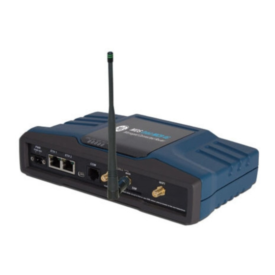
This guide provides installation and startup instructions for the
MDS Orbit Managed Connected Router(MCR) shown in Figure 1.
The MCR is a highly secure, industrial wireless solution for broad
based applications, including control center monitoring, well site
pad operations and video surveillance.
The unit provides wireless communication via multiple
technologies in a single, industrial package, without the need for
additional modules or add-ons. In addition, wired serial, Ethernet
and USB interfaces are provided at the front panel, reducing
network cost and complexity. Depending on order entry options the
unit may be equipped with a combination of Cell, Wi-Fi, and 900
MHz unlicensed FHSS/DTS radio.
Units are offered in two different interface offerings; 2 Ethernet/1
Serial (2E1S), or 2 Serial/1 Ethernet (2S1E). The 2E1S configura-
tion is the standard model and is shown here, although most infor-
mation applies equally to both configurations.
LED Indicator
Panel
Mini USB
Port
DC Power
Ethernet Ports
COM Port
(10-60 Vdc)
(RJ-45 10/100)
(RJ-45)
Antennas
(Aux & Main)
Figure 1. MCR Sample Unit, Showing Connectors & Indicators
1.1
Technical Manual
This Setup Guide covers basic installation and startup instructions
for the unit. A more detailed Technical Manual is also available
(05-6632A01). Refer to the Technical Manual for important
warnings, cautions and notes. GE MDS manuals, Setup guides,
Firmware, drivers and Application Notes are available free of
charge at www.gemds.com.
GE MDS has produced a series of instructional videos for
configuration and setup of the Orbit MCR products on YouTube.
These are available free of charge at: http://tinyurl.com/pey2ull.
2.0
INSTALLATION
2.1
Main Requirements
WARNING: When the unit is to be installed in hazardous locations,
use only the serial or Ethernet connections on the
unit's front panel. Do not use the USB port in
hazardous locations.
Figure 2
shows a typical installation of the unit. There are three
main requirements for installation:
• Adequate and stable primary power (10-60 VDC).
• Efficient and properly installed antennas for configured
options.
• Correct interface connections between the unit and associ-
ated data equipment.
05-6709A01, Rev. B
Invisible
place
holder
Cellular
SIM Card
WiFi Antenna
Slot
2.2
Installation Steps
Installation details for the product may vary, depending on
site-specific factors. The steps here provide the basic tasks
needed at most sites.
1. Mount the unit. Attach the supplied brackets to the bottom of
the case (if not already attached), using the screws provided.
Mounting bracket dimensions are shown in
Rail mounting brackets are to be used, consult the Technical
Manual for details.
NOTE: To prevent moisture from entering the unit, do not mount
the case with the cable connectors pointing up. Also,
dress all cables to prevent moisture from running along
the cables and into the enclosure.
Figure 2. Typical MCR Installation
Figure 3. Mounting Bracket Dimensions
2. Install the antennas and feedlines. The antennas used must
be designed to operate in the appropriate frequency band and
be mounted in a location providing a clear path to the associ-
ated station(s). Antennas should be mounted away from large
masses of metal and other obstructions.
GE MDS MCR Setup Guide
GE MDS MCR
(Equipment images may differ)
Setup Guide
Figure
3. If DIN
1
Advertisement
Table of Contents

Summary of Contents for GE MDS MCR
-
Page 1: Setup Guide
Firmware, drivers and Application Notes are available free of charge at www.gemds.com. GE MDS has produced a series of instructional videos for configuration and setup of the Orbit MCR products on YouTube. These are available free of charge at: http://tinyurl.com/pey2ull. -
Page 2: Unit Configuration
This connection can be made using the WiFi or Ethernet informa- Often, at least one of the antennas will be connected directly tion above. The initial sign-in prompt appears as shown below: to one of the coaxial connectors on the unit’s front panel. When remotely mounted antennas are used, coaxial feedlines should be low loss and be kept as short as possible. - Page 3 LED Functions then the green Save button at the top of the window. (If Verizon 4G, this field is pre-configured to vzwinternet.) Figure 8. LED Status Indicators Figure 6. Cell Basic Setup Info 05-6709A01, Rev. B GE MDS MCR Setup Guide...
-
Page 4: Com Port Reference
• Correct interface between the unit and other equipment GE MDS, LLC 175 Science Parkway Rochester, NY 14620 MDS Orbit MCR Setup Guide General Business: +1 585 242-9600 05-6709A01, Rev. B FAX: +1 585 242-9620 June 2014 (Copyright 2014, GE MDS, LLC) Web: www.gemds.com... - Page 5 Please con- connections on the unit’s front panel. Do tact GE MDS or your supplier for more information on the proper disposal not use the USB port in hazardous EXPLOSION of this equipment.
Need help?
Do you have a question about the MDS MCR and is the answer not in the manual?
Questions and answers