
Summary of Contents for Ayecka TC1
- Page 1 Transport Stream converter With Advanced DVB-S2 Receiver GigE Interface Operational Manual Rev 1.0...
- Page 2 Ayecka Communication Systems Ltd ., or its licensors, if any. All copies, so authorized, shall contain a full copy of this copyright notice.
-
Page 3: Table Of Contents
Application CPU ........................5 ASI ............................5 Quick Installation Guide ..................7 TC1 Functionality ....................9 TC1 Integration in Video over IP Networks ................9 TC1 Block Diagram ......................... 10 TC1 Receivers Management ....................10 TC1 SNMP MIB ........................11 TC1 Installation.................... - Page 4 10.12 Monitoring Parameters ......................47 10.13 Maintenance ........................47 10.14 Standard Compliance ......................47 TC1 Serial over USB Cable ................50 TC1 Software and Firmware Upgrade ............54 12.1 FPGA Image Management ....................54 12.2 Software Image Management ..................... 56 12.2.1...
- Page 5 Advanced DVB-S2 Receiver Operation Manual Release Notes ....................62 14.1 SW Release Notes for SW Version 1.02b84 ..............62 14.2 FPGA Release Notes for Version 2.02b010 ............... 62 14.3 Open Known Issues ......................62 SNMP MIB ...................... 64...
- Page 6 TC1 Operational Manual About this Document About this Document...
-
Page 7: Technical Support Contact Information
TC1 Operational Manual About this Document 1 Technical Support Contact Information For technical support please contact: Ayecka Communication systems LTD support@ayecka.com... -
Page 8: About This Document
The target audience for this document is satellite and digital video communication professionals. Purpose and Applicability This document introduces the setup, configuration, monitoring and troubleshooting of TC1. Applicable This document is applicable for the following SW and FW 2.3.1 Software – TC1 1.02b67 and above 2.3.2 Firmware –... - Page 9 TC1 Operational Manual TC1 Hardware TC1 Hardware...
-
Page 10: Tc1 Hardware
When the second Demodulator is in use, both Demodulators are limited to DVB-S2 8PSK CCM 30Msps. The configuration of demodulator operation mode is supported in the terminal menu and SNMP. Internal GigE Switch The TC1 architecture is based on an internal GigE switch. The switch has the following ports: Traffic: GigE port ... - Page 11 TC1 Operation Manual Quick Installation Guide Quick Installation Guide...
-
Page 12: Quick Installation Guide
Quick Installation Guide 4 Quick Installation Guide Follow the steps described in Table 1 to perform a Quick Installation of the TC1. After any change has been performed, enter 0 as many times required to return to the Main Menu. This will save the changes to the non-volatile RAM (for further details refer to Chapter 6). - Page 13 TC1 Operation Manual TC 1 – Functionality TC 1 – Functionality...
-
Page 14: Tc1 Functionality
The TC1 integration process is described as follows: The TC1 RF input is connected to the LNB on the satellite dish. TC1 provides the LNB with the appropriate power and control and receives the DVB-S/S2 signal in L-Band. ... -
Page 15: Tc1 Block Diagram
Management CPU: The management CPU implements the control of the board and the user interface. GigE Switch: The backbone of the TC1 is an internal managed GigE switch. The Internal switch is managed (QoS, VLAN etc). The interfaces are arranged, logically, as Ingress and Egress... -
Page 16: Tc1 Snmp Mib
Single RF input with single profile and single demodulator TC1 SNMP MIB The TC1 SNMP MIB provides the operator an interface to configure the device, monitor it and receive alerts (traps) on specific events. For further details on the MIB refer to Chapter 16, SNMP MIB on page 64. - Page 17 TC1 Operation Manual TC1 Installation TC1 Installation...
-
Page 18: Tc1 Installation
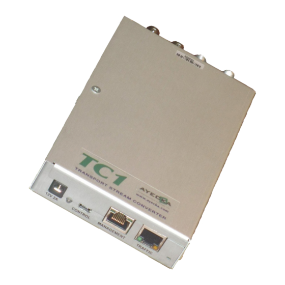
Plug the power adaptor into the AC power, with caution. Front Panel The front panel is the TC1 side that is connected to the different networks, is illustrated below. Figure 2 - TC1 Front Panel The following table describes the front panel interfaces:... - Page 19 Interface Description Type / Range Power LED Indication LED, indicating availability of Red - at the very TC1 startup after the DC power to the TC1 and Firmware power has been applied. The programming state. constant red coloring indicates that TC1 application software has been launched.
-
Page 20: Back Panel
Gennum GS9074A ASI Lock ASI input status LED Green when the ASI input is locked Table 3 - TC1 Back Panel Interfaces Note ASI out and ASI in are optional interfaces. For more information please contact Ayecka sales at sales@ayecka.com. -
Page 21: Installation Procedure
Management interface: For further details refer to 8.3.3 Ingress: For further details refer to 0Egress: For further details refer to 8.3.1.2 Cables Connection Connect the cables to the TC1 in the following order: Management ... - Page 22 TC1 Operation Manual TC1 Configuration and Management TC1 Configuration and Management...
-
Page 23: Tc1 Configuration And Management
UI Telnet Interface The TC1 provides a Telnet over IP interface. The Telnet is use to interface with the terminal based UI. Telnet is password protected. Default password is “telnet”. To modify the telnet password see paragraph 8.3.4.5... - Page 24 TC1 Operation Manual TC1 User Interface TC1 User Interface...
-
Page 25: Tc1 User Interface
Ayecka TC1c bootloader version 1.01b6 Looking for TC1 application software... A valid TC1 application software found. Checking whether Upgrade Mode entry is requested... No Launching TC1 application software at 0x 00005000 Programming FPGA ... The text includes the bootloader version... -
Page 26: Main Menu
30AAB – Indicates the demodulator type – BAB is for Broadcast and AAB for Advance. 30 for cut 3.0. Note The example above refers to TC1 with dual receivers. In case of single receiver, the 2nd line will not appear. -
Page 27: Configuration Menu
TC1 Operation Manual TC1 User Interface 8.3.1 Configuration Menu The Configuration Menu configures the TC1 Ingress ( the two DVB-S2 inputs and ASI input) and Egress (ASI output and Multicast over GigE). To access the configuration menu: From the Main menu, select Configuration. The configuration menu is displayed, as... -
Page 28: Rx Channel Switching
TC1 Operation Manual TC1 User Interface 8.3.1.1.2 RX Channel Switching The RX Channel Switching menu configures if changing RX will be automatic (in round robin fashion) or active RX will not change. Note: The RX Channel Switching menu is disabled when the Rx Channel operation mode is configured to Dual Mode in the previous section. -
Page 29: Select Active Rx Channel
TC1 Operation Manual TC1 User Interface 8.3.1.1.2.1 RX Channel Switch Mode To define the RX Channel Switch Mode: From the RX Channel Switch Configuration Management, select 1 to configure the RX Channel Switch Mode. The RX Channel Switch Mode window is displayed:... -
Page 30: Rx Channel Configuration Menu
Each RX channel (Physical channel) supports two configuration sets. The selection of configuration set can be manual or automatic. In Automatic mode the TC1 will try to lock using one configuration set for configured period of time. If it fails to lock, it will try the other configuration set. - Page 31 Manual: Select 2 to define the configuration profile to be in manual mode. Note: When Automatic mode, the TC1 will change profile after the defined Profile Switch period in seconds. 8.3.1.1.4.1.2 RX Channel Configuration Sets Management: Profile Switch Period To define the RX Channel Configuration Sets Management Profile Switch Perio: ...
- Page 32 Configuration menu. In order to cancel the manual symbol rate configuration and enable the TC1 to auto- detect the symbol rate, the symbol rate value in the Configuration menu should be explicitly annulled.
- Page 33 MODCOD (MODCODE) The TC1 display the signal’s roll off Roll Off Pilot The TC1 display if Pilot is exist in the received signal The TC1 display the signal’s spectral inversion Spectral Inversion 0 – 262141. Gold Code Configure DVB-S2 PL scrambling Gold code...
- Page 34 TC1 Operation Manual TC1 User Interface Table 4 - TC1 Rx channels configurable parameters...
-
Page 35: Egress Configuration
1. RX1 Egress Configuration 2. RX2 Egress Configuration 3. ASI Egress Configuration 8.3.1.2.1 RX1 Egress Configuration The RX1 Egress Configuration Menu configures the output from the TC1 Rx1 input RX1 Egress Configuration ======================== 1. Destination Ethernet Address 01-00-5E-01-01-01 2. Source Ethernet Address CC-F6-7A-04-CE-8E 3. -
Page 36: 802.1Q Vlan Configuration
Configure the transport stream over IP encapsulation parameters Parameters Enabled Enables or disables the output Table 5 - TC1 Egress channel configurable parameters 8.3.1.2.1.1 802.1Q VLAN Configuration The 802.1Q VLAN Configuration Menu configures the relevant fields in the outgoing Ethernet packets 802.1Q VLAN Configuration ========================= 1. -
Page 37: Calculating Multicast Destination Mac
TC1 Operation Manual TC1 User Interface 8.3.1.2.1.3 Calculating Multicast Destination MAC For multicast packets the DST MAC address is derived from the DSt IP address Multicast MAC address are In the range of 01-00-5E-00-00-00 to 01-00-5E-7F-FF-FF 225.1.1.1 will become 01-00-5E-01-01-01,... -
Page 38: Status Menu
TC1 Operation Manual TC1 User Interface 8.3.2 Status Menu From the Status menu, select the required status (channel #1 or #2): Status ====== 1. RX Channel 1 2. RX Channel 2 Selecting one of the channels displays the relevant status information. The Status display is automatically updated every 3 seconds. - Page 39 Demodulator lock: Lock on DVB-S / DVB-S2 signal Transport Lock: Transport stream is received with IP packets on it (valid MPE). The Transport stream will stay unlock until first IP packets will pass through the TC1. Demodulator Es/No: Provides information about the RF signal quality ...
-
Page 40: Network Menu
Management Port State: Enable or disable the management Ethernet physical port Air (satellite) Interface: IP address of the TC1 CPU for IP packets received from the Satellite link. Packets distained to the CPU air IP address will be delivered ONLY to the... -
Page 41: System Menu
The Cold reset restarts the controller, reloads the FPGA and restarts the internal switch. 8.3.4.3 Restore factory Defaults The Restore Factory Defaults and Reset configures the TC1 to the values set in production, deleting all configurations performed later. 8.3.4.4 User Name... - Page 42 To view the FPGA upgrade menu select C from the system. FPGA Upgrade ============ 1. TFTP Server IP Address: 10.0.0.85 2. Filename: TC1_FPGA.afp 3. Show installed versions 4. Start the upload procedure .שגיאה! מקור ההפניה לא נמצא For further information refer to Chapter : TC1 Software and Firmware Upgrade procedure...
- Page 43 .שגיאה! מקור ההפניה לא נמצא – about the For further information refer to Chapter Software Upgrade procedure. 8.3.4.12.1 Show Installed Versions Menu The Show the installed version menu, enables viewing the Software images stored in the TC1 non volatile RAM: Software Versions ================= Index...
- Page 44 For further details about the software Upgrade procedure, refer to Chapter .ההפניה לא נמצא 8.3.4.13 Hardware Information Menu The TC1 Board Hardware Information menu is displayed, as follows: TC1 Board Hardware Information ============================== Permanent Storage Device: Numonyx Serial Flash Memory M25PX16 16...
-
Page 45: Statistics
TC1 Operation Manual TC1 User Interface 8.3.5 Statistics... -
Page 46: Trouble Shooting
TC1 Operation Manual Trouble Shooting Trouble Shooting... -
Page 47: General
The LAN interface reply to Ping only from the default gateway. The TC1 sends an ARP request to the default gateway. In case of 3 consecutive failures to receive the ARP reply, the TC1 will retry to restart the GigE interface. -
Page 48: No Ip Traffic On Egress
TC1 Operation Manual Trouble Shooting No IP traffic on Egress If no transport stream over IP traffic is present on the GigE please verify : RF lock Egress of the correct Ingress is configured MAC address of the Multicast IP is correct... - Page 49 TC1 Operation Manual TC1 Specifications TC1 Specifications...
-
Page 50: Tc1 Specifications
TC1 Operation Manual TC1 Specifications 10 TC1 Specifications Specifications may vary with different versions of the TC1. For further details, please contact Ayecka. Receiver DVB-S2 Mode 10.1 The Receiver DVB-S2 Mode includes the following specifications: Mbodulation: QPSK, 8PSK, 16APSK, 32APSK (limited to 8PSK CCM in dual demodulator mode). -
Page 51: Data Interface
TC1 Operation Manual TC1 Specifications Data Interface 10.5 The Data Interface includes the following specifications Speed: 100/1000 BaseT. Auto speed Packet handling: L3 Internal Switch: GigE managed switch Environmental Conditions 10.6 The Environmental Conditions include the following specifications: ... -
Page 52: Control And Monitoring
TC1 Operation Manual TC1 Specifications Control and Monitoring 10.10 The Control and Monitoring specifications include the following: Serial port: Serial over USB with terminal based UI IP: Telnet with terminal based UI IP: SNMP Configuration Parameters 10.11 The configuration parameters include the following: ... - Page 53 TC1 Operation Manual TC1 Serial over USB Cable TC1 Serial over USB Cable...
-
Page 55: Tc1 Serial Over Usb Cable
Note: Connect the TC1 Mini USB cable ONLY after completion of the drivers installation After the drivers are installed and the TC1 is connected, the Virtual Com will be added to the devices on the client PC. Use the Device Manager to verify the installation and to obtain the Virtual port number. Figure 4, below shown an example where the Virtual COM port is COM3. - Page 56 .על הטקסט שברצונך שיופיע כאן Heading 1 Figure 5, below demonstrates how to use Windows® HyperTerminal: Figure 5 - TC1 Terminal COM Port Selection After the COM Port is selected, set the COM properties 115200,8,N,1 Figure 6 below, demonstrate the COM properties settings...
- Page 57 שגיאה! השתמ .על הטקסט שברצונך שיופיע כאן Heading 1 After the HyperTerminal is configured, enter 0 to initiate communication with the TC1. Figure 7 displays how the terminal should look if all was set correctly. Figure 7 - TC1 User interface Note For further information about the user interface, refer to Chapter 8.
- Page 58 Advanced DVB-S2 Receiver Operational Manual שגיאה! השתמש בכרטיסיה בית כדי להחיל .על הטקסט שברצונך שיופיע כאן Heading 1 TC1 Software and Firmware Upgrade...
-
Page 59: Tc1 Software And Firmware Upgrade
FPGA Image Management 12.1 At boot, either after a power cycle or cold reset, the TC1 loads the firmware image to the FPGA. This process takes less then 5 seconds. The TC1 stores two images of the Firmware, where one is set to be active and used to configure the FPGA at the boot or restart. The file type for Firmware upgrade using TFTP is XXX.afp... - Page 60 Select 4.Start the upload procedure, the TC1 requests confirmation, as follows: FPGA Upgrade - Are you sure (Y/N)? Click Y. The TC1 formats the storage area, and the following is displayed. Formatting Permanent Storage... The TFTP process will then be initiated.
-
Page 61: Software Image Management
Flash Magic. Flash Magic for NXP controllers is freely available from http://www.flashmagictool.com/ At boot time the TC1 boot loader verifies whether a new software image was selected as active and performs the following: ... -
Page 62: Software Image Upgrade Using Tftp
Reboot or power cycle. When the TC1 reboots and detects a new image on the Flash memory, it copies it to the CPU internal Flash memory (indicating the copy of each sector with a dot on the display): Ayecka TC1c bootloader version 1.01b6... - Page 63 Retalix Management Service Transition Plan השתמש בכרטיסיה בית כדי להחיל !שגיאה .על הטקסט שברצונך שיופיע כאן Heading 1 Safety...
-
Page 64: Safety
The TC1 operates from 12V DC with an external power supply. The TC1 has been shown to comply with the EN 60950 Safety of Information Technology Equipment (Including Electrical Business Machines) To avoid chance for risk please follow the instructions below: ... - Page 65 Retalix Management Service Transition Plan שגיאה! השתמש בכרטיסיה בית כדי להחיל .על הטקסט שברצונך שיופיע כאן Heading 1 Release Notes...
-
Page 67: Sw Release Notes For Sw Version 1.02B
Retalix Management Service Transition Plan שגיאה! השתמש בכרטיסיה בית כדי להחיל .על הטקסט שברצונך שיופיע כאן Heading 1 14 Release Notes SW Release Notes for SW Version 1.02b84 14.1 Feature / known issue Note Release # Adding note when configuration User need to select Y or N to continue. - Page 68 Retalix Management Service Transition Plan שגיאה! השתמש בכרטיסיה בית כדי להחיל .על הטקסט שברצונך שיופיע כאן Heading 1 SNMP MIB...
- Page 69 Advanced DVB-S2 Receiver Operational Manual שגיאה! השתמש בכרטיסיה בית כדי להחיל .שיופיע כאן על הטקסט שברצונך Heading 1 15 SNMP MIB For the SNMP MIB of the TC1 please contact info@ayecka.com.
Need help?
Do you have a question about the TC1 and is the answer not in the manual?
Questions and answers