Table of Contents
Advertisement
Advertisement
Table of Contents

Subscribe to Our Youtube Channel
Related Manuals for ASROCK FM2A78M Pro3+


Summary of Contents for ASROCK FM2A78M Pro3+
- Page 1 FM2A78M Pro3+ FM2A78M Pro3+ F M 2 A 7 8 M P r o 3 + F M 2 A 7 8 M P r o 3 +...
-
Page 2: Copyright Notice
(including damages for loss of proits, loss of business, loss of data, interruption of business and the like), even if ASRock has been advised of the possibility of such damages arising from any defect or error in the documentation or product. -
Page 3: Table Of Contents
Dual Graphics Operation Guide ..........20 3. Software and Utilities Operation ....... 22 Installing Drivers ................ 22 A-Tuning ..................23 ASRock APP Shop ..............29 Start8 ..................35 4. UEFI SETUP UTILITY ..........38 Introduction ................38 4.1.1 UEFI Menu Bar ..............38 4.1.2 Navigation Keys ............... - Page 4 Exit Screen ................59...
-
Page 5: Introduction
ASRock website without further notice. You may ind the latest VGA cards and CPU support lists on ASRock website as well. ASRock website http://www.asrock.com... -
Page 6: Speciications
1.2 Speciications Platform - Micro ATX Form Factor - Solid Capacitor design - High Density Glass Fabric PCB - Supports Socket FM2+ 95W / FM2 100W processors Chipset - AMD A78 FCH (Bolton-D3) Memory - Dual Channel DDR3 Memory Technology - 4 x DDR3 DIMM Slots - Supports DDR3 2400+(OC)/2133/1866/1600/1333/1066 non-ECC, un-buffered memory (see CAUTION 1) - Page 7 - 1 x D-Sub Port - 1 x DVI-D Port - 1 x HDMI Port - 4 x USB 2.0 Ports (Supports ESD Protection (ASRock Full Spike Protection)) - 2 x USB 3.0 Ports (AMD A78 FCH (Bolton-D3)) (Supports ESD Protection (ASRock Full Spike Protection))
- Page 8 Certiications - FCC, CE, WHQL - ErP/EuP ready (ErP/EuP ready power supply is required) * For detailed product information, please visit our website: http://www.asrock.com WARNING Please realize that there is a certain risk involved with overclocking, including adjusting the setting in the BIOS, applying Untied Overclocking Technology, or using third-party overclocking tools.
- Page 9 2400/2133/1866/1600 memory module on this motherboard, please refer to the memory support list on our website for the compatible memory modules. ASRock website http://www.asrock.com 2. Due to the operating system limitation, the actual memory size may be less than 4GB for the reservation for system usage ®...
-
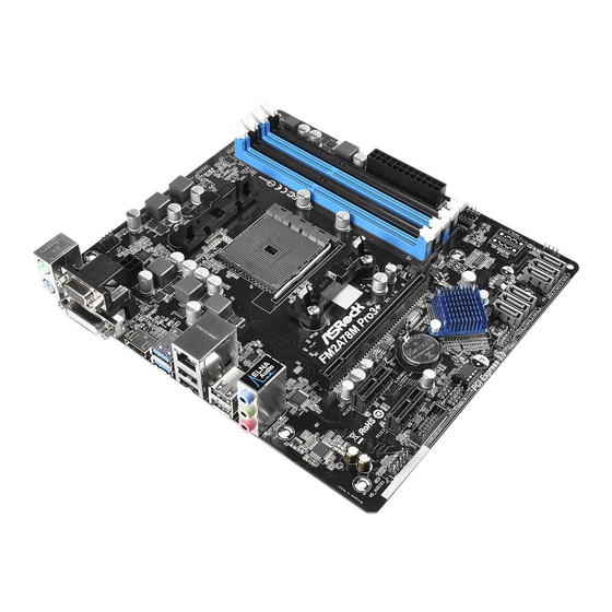
Page 10: Motherboard Layout
1.3 Motherboard Layout CPU_FAN1 ATX12V1 USB 3.0 T: USB0 B: USB1 USB 2.0 Top: T: USB2 RJ-45 B: USB3 USB 2.0 T: USB4 B: USB5 TPMS1 SPEAKER1 FM2A78M Pro3+ PCIE1 CLRCMOS1 PCIE2 CMOS A78 FCH BATTERY (Bolton-D3) RoHS Chipset SATA_1 SATA_2 SATA_3 SATA_4... - Page 11 No. Description ATX 12V Power Connector (ATX12V1) CPU Fan Connector (CPU_FAN1) 2 x 240-pin DDR3 DIMM Slots (DDR3_A1, DDR3_B1) 2 x 240-pin DDR3 DIMM Slots (DDR3_A2, DDR3_B2) ATX Power Connector (ATXPWR1) TPM Header (TPMS1) Chassis Speaker Header (SPEAKER1) Chassis Fan Connector (CHA_FAN1) SATA3 Connector (SATA_6) 10 SATA3 Connector (SATA_5) SATA3 Connector (SATA_4) SATA3 Connector (SATA_3)
-
Page 12: I/O Panel
1.4 I/O Panel No. Description No. Description PS/2 Mouse Port USB 2.0 Ports (USB4_5)** D-Sub Port USB 2.0 Ports (USB23)** USB 3.0 Ports (USB_01) LAN RJ-45 Port* (AMD A78 FCH (Bolton-D3)) Line In (Light Blue) HDMI Port DVI-D Port Front Speaker (Lime) Microphone (Pink) PS/2 Keyboard Port * There are two LEDs on the LAN port. -
Page 13: Installation
2. Installation This is a Micro ATX form factor motherboard. Before you install the motherboard, study the coniguration of your chassis to ensure that the motherboard its into it. Pre-installation Precautions Take note of the following precautions before you install motherboard components or change any motherboard settings. Before you install or remove any component, ensure that the power is switched off or the power cord is detached from the power supply. -
Page 14: Cpu Installation
2.1 CPU Installation Step 1. Unlock the socket by lifting the lever up to a 90 angle. Step 2. Position the CPU directly above the socket such that the CPU corner with the golden triangle matches the socket corner with a small triangle. Step 3. -
Page 15: Installation Of Cpu Fan And Heatsink
2.2 Installation of CPU Fan and Heatsink After you install the CPU into this motherboard, it is necessary to install a larger heatsink and cooling fan to dissipate heat. You also need to spray thermal grease between the CPU and the heatsink to improve heat dis- sipation. -
Page 16: Installation Of Memory Modules (Dimm)
2.3 Installation of Memory Modules (DIMM) This motherboard provides four 240-pin DDR3 (Double Data Rate 3) DIMM slots, and supports Dual Channel Memory Technology. 1. For dual channel coniguration, you always need to install identical (the same brand, speed, size and chip-type) DDR3 DIMM pairs. 2. -
Page 18: Expansion Slots (Pci Express Slots)
2.4 Expansion Slots (PCI Express Slots) There are 3 PCI Express slots on this motherboard. Before installing an expansion card, please make sure that the power supply is switched off or the power cord is unplugged. Please read the documenta- tion of the expansion card and make necessary hardware settings for the card before you start the installation. -
Page 19: Jumpers Setup
2.5 Jumpers Setup The illustration shows how jumpers are setup. When the jumper cap is placed on pins, the jumper is “Short”. If no jumper cap is placed on pins, the jumper is “Open”. The illustration shows a 3-pin jumper whose pin1 and pin2 are “Short”... -
Page 20: Onboard Headers And Connectors
2.6 Onboard Headers and Connectors Onboard headers and connectors are NOT jumpers. Do NOT place jumper caps over these headers and connectors. Placing jumper caps over the headers and connectors will cause permanent damage of the motherboard! Serial ATA3 Connectors These six Serial ATA3 (SATA3) connectors support (SATA_1: see p.6, No. - Page 21 Front Panel Audio Header This is an interface for the front PRESENCE# panel audio cable that allows MIC_RET (9-pin HD_AUDIO1) OUT_RET convenient connection and (see p.6 No. 19) control of audio devices. OUT2_L J_SENSE OUT2_R MIC2_R MIC2_L 1. High Deinition Audio supports Jack Sensing, but the panel wire on the chassis must support HDA to function correctly. Please follow the instruction in our manual and chassis manual to install your system.
- Page 22 HDLED (Hard Drive Activity LED): Connect to the hard drive activity LED on the chassis front panel. The LED is on when the hard drive is reading or writing data. The front panel design may differ by chassis. A front panel module mainly consists of power switch, reset switch, power LED, hard drive activity LED, speaker and etc.
- Page 23 Though this motherboard provides 24-pin ATX power connector, it can still work if you adopt a traditional 20-pin ATX power supply. To use the 20-pin ATX power supply, please plug your power supply along with Pin 1 and Pin 13. 20-Pin ATX Power Supply Installation ATX 12V Power Connector Please connect an ATX 12V...
-
Page 24: Amd Dual Graphics Operation Guide
2.7 AMD Dual Graphics Operation Guide This motherboard supports AMD Dual Graphics feature. AMD Dual Graphics brings multi-GPU performance capabilities by enabling an AMD A78 FCH (Bolton-D3) integrated graphics processor and a discrete graphics processor to operate simultaneously with combined output to a single display for blisteringly-fast frame ®... - Page 25 Step 7. You can also click “AMD VISION Engine Control Center” on your taskbar to enter AMD VISION Engine Control Center. ® Windows AMD VISION Engine Control Center Step 8. In AMD VISION Engine Control Center, please choose “Performance”. Click “AMD CrossFire ”. Step 9. Click “Enable CrossFire ” and click “Apply“ to save your change. Step 10. Reboot your system. Then you can freely enjoy the beneit of Dual Graphics feature. * Dual Graphics appearing here is a registered trademark of AMD Technologies Inc., and is used only for identiication or explanation and to the owners’ beneit, without intent to infringe.
-
Page 26: Software And Utilities Operation
3. Software and Utilities Operation 3.1 Installing Drivers The Support CD that comes with the motherboard contains necessary drivers and useful utilities that enhance the motherboard’s features. Running The Support CD To begin using the support CD, insert the CD into your CD-ROM drive. The CD automatically displays the Main Menu if “AUTORUN”... -
Page 27: A-Tuning
A-Tuning is ASRock’s multi purpose software suite with a new interface, more new features and improved utilities, including XFast RAM, Dehumidi- ier, Good Night LED, FAN-Tastic Tuning, OC Tweaker and a whole lot more. 3.2.1 Installing A-Tuning When you install the all-in-one driver to your system from ASRock’s support CD, A-Tuning will be auto-installed as well. After the installation, you will ind the icon “A-Tuning“ on your desktop. Double-click the “A-Tuning“ icon, A-Tuning main menu will pop up. -
Page 28: Fast Boot
Tools Various tools and utilities. XFast RAM Boost the system’s performance and extend the HDD’s or SDD’s lifespan! Create a hidden partition, then assign which iles should be stored in the RAM drive. ® *This function supports Windows 64-bit OS only. XFast LAN Boost the speed of your internet connection! Select a speciic mode for making the designated program's priority highest. Fast Boot Fast Boot minimizes your computer's boot time. Please note that Ultra Fast mode is only supported by Windows 8.1/8 and the VBIOS must support UEFI GOP if you are using an external graphics card. - Page 29 FAN-Tastic Tuning Conigure up to ive different fan speeds using the graph. The fans will automatically shift to the next speed level when the assigned temperature is met. Dehumidiier Prevent motherboard damages due to dampness. Enable this function and conigure the period of time until the computer powers on, and the duration of the dehumidifying process. USB Key Plug in the USB Key and let your computer log in to windows automatically! OC DNA OC DNA is an unique software which helps to save your OC settings as a proile. Then you can send this OC setting proile to the friends.
-
Page 30: System Info
OC Tweaker Conigurations for overclocking the system. System Info View information about the system. *The System Browser tab may not appear for certain models. -
Page 31: Live Update
Live Update Check for newer versions of BIOS or drivers. Tech Service Contact Tech Service if you have problems with your computer. Please leave your contact information along with details of the problem. - Page 32 Settings Conigure ASRock A-Tuning. Click to select "Auto run at Windows Startup" if you want A-Tuning to be launched when you start up the Windows operating system.
-
Page 33: Asrock App Shop
Double-click on your desktop to access ASRock APP Shop utility. *You need to be connected to the Internet to download apps from the ASRock APP Shop. 3.3.1 UI Overview Category Panel... - Page 34 3.3.2 Apps When the "Apps" tab is selected, you will see all the available apps on screen for you to download. Installing an App Step 1 Find the app you want to install. The most recommended app appears on the left side of the screen. The other various apps are shown on the right.
- Page 35 Step 3 If you want to install the app, click on the red icon to start downloading. Step 4 When installation completes, you can ind the green "Installed" icon appears on the upper right corner. To uninstall it, simply click on the trash can icon *The trash icon may not appear for certain apps.
- Page 36 Upgrading an App You can only upgrade the apps you have already installed. When there is an available new version for your app, you will ind the mark of "New Version" appears below the installed app icon. Step 1 Click on the app icon to see more details. Step 2 Click on the yellow icon to start upgrading.
- Page 37 3.3.3 BIOS & Drivers Installing BIOS or Drivers When the "BIOS & Drivers" tab is selected, you will see a list of recommended or critical updates for the BIOS or drivers. Please update them all soon. Step 1 Please check the item information before update. Click on to see more details.
- Page 38 3.3.4 Setting In the "Setting" page, you can change the language, select the server location, and determine if you want to automatically run the ASRock APP Shop on Windows startup.
-
Page 39: Start8
Install Start8, which is located in the folder at the following path of the Sup- , which is located in the folder at the following path of the Sup- port CD: \ ASRock Utility > Start8. 3.4.2 Coniguring Start8 Style Select between the Windows 7 style and Windows 8 style Start Menu. - Page 40 Conigure Conigure provides coniguration options, including icon sizes, which shortcuts you want Start Menu to display, quick access to recently used apps, the functionality of the power button, and more. Control...
- Page 41 Control lets you conigure what a click on the start button or a press on the Windows key does. Desktop Desktop allows you to disable the hot corners when you are working on the desktop. It also lets you choose whether or not the system boots directly into desktop mode and bypass the Metro user interface. About Displays information about Start8.
-
Page 42: Uefi Setup Utility
4. UEFI SETUP UTILITY 4.1 Introduction ASRock Interactive UEFI is a blend of system coniguration tools, cool sound ef- fects and stunning visuals. Not only will it make BIOS setup less dificult but also a lot more amusing. This section explains how to use the UEFI SETUP UTILITY to conigure your system. The UEFI chip on the motherboard stores the UEFI SETUP UTILITY. You may run the UEFI SETUP UTILITY when you start up the computer. -
Page 43: Navigation Keys
4.1.2 Navigation Keys Please check the following table for the function description of each navigation key. Navigation Key(s) Function Description Moves cursor left or right to select Screens Moves cursor up or down to select items + / - To change option for the selected items <Tab>... -
Page 44: Oc Tweaker Screen
4.3 OC Tweaker Screen In the OC Tweaker screen, you can set up overclocking features. EZ OC Mode You can use this option to adjust EZ overclocking setting. Please note that overclocing may cause damage to your components and motherboard. It should be done at your own risk and expense. - Page 45 Processor Maximum Frequency It will display Processor Maximum Frequency for reference. Processor Maximum Voltage It will display Processor Maximum Voltage for reference. Multiplier/Voltage Change This item is set to [Auto] by default. If it is set to [Manual], you may adjust the value of Processor Frequency and Processor Voltage. However, it is recommended to keep the default value for system stability. Boost Frequency Multiplier For safety and system stability, it is not recommended to adjust the value of this item.
- Page 46 DRAM Timing Control DRAM Slot Use this item to view SPD data. DRAM Timing Control Use this item to control DRAM timing. Power Down Enable Use this item to enable or disable DDR power down mode. Bank Interleaving Interleaving allows memory accesses to be spread out over banks on the same node, or accross nodes, decreasing access contention.
-
Page 47: Advanced Screen
4.4 Advanced Screen In this section, you may set the conigurations for the following items: CPU Conigu- ration, Nouth Bridge Coniguration, South Bridge Coniguration, Storage Conigura- tion, ACPI Coniguration, USB Coniguration and Trusted Computing. Setting wrong values in this section may cause the system to malfunction. -
Page 48: Cpu Coniguration
4.4.1 CPU Coniguration Core C6 Mode Use this item to enable or disable Core C6 mode. The default value is [Enabled]. Package C6 Mode This item appears only when you enable the item “Core C6 Mode”. Use this item to enable or disable Package C6 mode. The default value is [Dis- abled]. -
Page 49: North Bridge Coniguration
4.4.2 North Bridge Coniguration IOMMU This allows you to enable or disable IOMMU support. Primary Graphics Adapter This item will switch the PCI Bus scanning order while searching for video card. It allows you to select the type of Primary VGA in case of multiple video controllers. -
Page 50: South Bridge Coniguration
4.4.3 South Bridge Coniguration Onboard HD Audio Select [Auto], [Enabled] or [Disabled] for the onboard HD Audio feature. Front Panel Select [Auto] or [Disabled] for the onboard HD Audio Front Panel. Onboard LAN This allows you to enable or disable the onboard LAN feature. Good Night LED Enable this option to turn off Power LED when the system is power on. -
Page 51: Storage Coniguration
4.4.4 Storage Coniguration SATA Controller Use this item to enable or disable the “SATA Controller” feature. SATA Mode Use this item to adjust SATA Mode. The default value of this option is [AHCI Mode]. Coniguration options: [AHCI Mode], [RAID Mode] and [IDE Mode]. If you set this item to RAID mode, it is suggested to install SATA ODD driver on SATA_5 and SATA_6 ports. -
Page 52: Acpi Coniguration
4.4.5 ACPI Coniguration Suspend to RAM Use this item to select whether to auto-detect or disable the Suspend-to- RAM feature. Select [Auto] will enable this feature if the OS supports it. Check Ready Bit Enable to enter the operating system after S3 only when the hard disk is ready, this is recommended for better system stability. - Page 53 USB Keyboard/Remote Power On Use this item to enable or disable USB Keyboard/Remote to power on the system. USB Mouse Power On Use this item to enable or disable USB Mouse to power on the system. ACPI HPET table Use this item to enable or disable ACPI HPET Table. The default value is [Enabled].
-
Page 54: Usb Coniguration
4.4.6 USB Coniguration USB Controller Use this item to enable or disable the use of USB controller. A78 USB 3.0 Controller Use this item to enable or disable the use of USB 3.0 controller. Legacy USB Support Use this option to select legacy support for USB devices. There are four coni guration options: [Enabled], [Auto], [Disabled] and [UEFI Setup Only]. -
Page 55: Trusted Computing
4.4.7 Trusted Computing Security Device Support Enable to activate Trusted Platform Module (TPM) security for your hard disk drives. -
Page 56: Tool
OMG, guest accounts without permission to modify the system time are required. UEFI Tech Service Contact ASRock Tech Service if you are having trouble with your PC. Please setup network coniguration before using UEFI Tech Service. Easy RAID Installer Easy RAID Installer helps you to copy the RAID driver from the support CD to your USB storage device. -
Page 57: Network Coniguration
UEFI ile to your USB lash drive, loppy disk or hard drive and launch this tool, then you can update your UEFI only in a few clicks without prepar- ing an additional loppy diskette or other complicated lash utility. Please be noted that the USB lash drive or hard drive must use FAT32/16/12 ile system. If you execute Instant Flash utility, the utility will show the UEFI iles and their respective information. Select the proper UEFI ile to up- date your UEFI, and reboot your system after the UEFI update process is completed. - Page 58 Dehumidiier Duration This allows users to conigure the duration of the dehumidifying process before it returns to S4/S5 state. Dehumidiier CPU Fan Setting Use this setting to conigure CPU fan speed while “Dehumidiier” is en- abled. Would you like to save current setting user defaults? In this option, you are allowed to load and save three user defaults according to your own requirements.
-
Page 59: Hardware Health Event Monitoring Screen
4.6 Hardware Health Event Monitoring Screen In this section, it allows you to monitor the status of the hardware on your system, including the parameters of the CPU temperature, motherboard temperature, CPU fan speed, chassis fan speed, and the critical voltage. CPU Fan 1 Setting Select a fan mode for CPU Fan 1, or choose Customize to set 5 CPU tem- peratures and assign a respective fan speed for each temperature. -
Page 60: Boot Screen
4.7 Boot Screen In this section, it will display the available devices on your system for you to conig- ure the boot settings and the boot priority. Fast Boot Fast Boot minimizes your computer’s boot time. There are three con- iguration options: [Disabled], [Fast] and [Ultra Fast]. The default value is [Disabled]. Please refer to below descriptions for the details of these three options: [Disabled] - Disable Fast Boot. [Fast] - The only restriction is you may not boot by using an USB lash drive. - Page 61 AddOn ROM Display Enable AddOn ROM Display to see the AddOn ROM messages or conig- ure the AddOn ROM if you’ve enabled Full Screen Logo. Disable for faster boot speed. Boot Failure Guard Enable or disable the feature of Boot Failure Guard. Boot Failure Guard Count Enable or disable the feature of Boot Failure Guard Count. CSM (Compatibility Support Module) Enable to launch the Compatibility Support Module.
-
Page 62: Security Screen
4.8 Security Screen In this section, you may set or change the supervisor/user password for the system. For the user password, you may also clear it. Secure Boot ® Enable to support Windows 8 / 8.1 Secure Boot. -
Page 63: Exit Screen
4.9 Exit Screen Save Changes and Exit When you select this option, it will pop-out the following message, “Save coniguration changes and exit setup?” Select [OK] to save the changes and exit the UEFI SETUP UTILITY. Discard Changes and Exit When you select this option, it will pop-out the following message, “Discard changes and exit setup?”... -
Page 64: Contact Information
Contact Information If you need to contact ASRock or want to know more about ASRock, you’re welcome to visit ASRock’s website at http://www.asrock.com; or you may contact your dealer for further information. For technical questions, please submit a support request form at http://www.asrock.com/support/tsd.asp...
Need help?
Do you have a question about the FM2A78M Pro3+ and is the answer not in the manual?
Questions and answers