Advertisement
Three Stages
BATTERY CHARGER
BC–012–20A
SERVICE MANUAL
Qualified personnel who are familiar with the risks involved
and relevant regulations may only carry out maintenance and
repair work.
To avoid electrical shock and short circuit causing
component damage, disconnect input power cable before
working on the device. Safety instructions are required to be
observed at all times.
Warning!
Advertisement
Table of Contents

Subscribe to Our Youtube Channel
Summary of Contents for Power Saver BC–012–20A
-
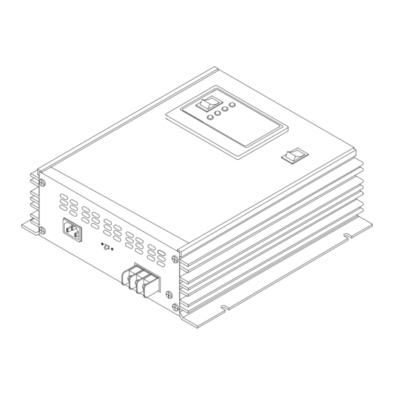
Page 1: Battery Charger
Three Stages BATTERY CHARGER BC–012–20A SERVICE MANUAL Warning! Qualified personnel who are familiar with the risks involved and relevant regulations may only carry out maintenance and repair work. To avoid electrical shock and short circuit causing component damage, disconnect input power cable before working on the device. - Page 2 CONTENTS ASSEMBLY DRAWING SYSTEM BLOCK DIAGRAM TROUBLESHOOTING Problems & Solutions PCB Connection and Part List Checking Procedures TS3~TS4 COMPONENT LOCATION CALIBRATION PROCEDURES SCHEMATIC DIAGRAM SD1~SD3...
-
Page 6: Troubleshooting Guide
TROUBLESHOOTING GUIDE A. Assembly procedures Follow the assembly drawing AS1, remove the cover and keep all parts for further assembly. 1. Remove SC1 x 4 2. Remove SC2 3. Disconnect CN8 4. Remove PN1 lower cover 5. Disconnect CN2, CN3, CN5 and CN7. 6. -
Page 7: Parts List
TROUBLESHOOTING GUIDE B. PC Board Connection: Modules Symbolic implications GROUND LED DISPLAY BOARD BATTERY SELECTOR COOLING FAN MAIN BOARD VOLTAGE SELECTOR POWER SUPPLY SELECTOR TO MAIN PC BOARD CN7 LED DISPLAY BOARD C. PARTS LIST Main PC Board: 1. T1 : TRANSFORMER 2. -
Page 8: Equipment Setup
TROUBLESHOOTING GUIDE D. Equipment Setup: Perform the following checking procedures, setup the equipment as followings: 1. DC Power Supply 1.5A or above , set to 12.0VDC. 2. Oscilloscope (OSC) 20MHz or above x 1 Set the Time/Div to 2.0 us and set the Volt/Div to 2 Vdc. 3. -
Page 10: Calibration Procedures
Battery charger calibration procedures A. Equipment Setup: Perform the following calibration procedures, setup the equipment as followings: 1. Adjustable Electronic Load, 30A 30VDC or above. 2. Digital Multi-Meter (DVM). B. Calibration procedures: 1. Check insulation tape must good condition on the heatsink both sides. Replace new tape if any damaged.
Need help?
Do you have a question about the BC–012–20A and is the answer not in the manual?
Questions and answers