Table of Contents
Advertisement
Quick Links
Advertisement
Table of Contents

Summary of Contents for Lynx 4S
- Page 1 OPERATION MANUAL...
-
Page 2: Table Of Contents
MANUAL: SECTION 1 Table of Contents Section 1: Introduction Introduction....................................04 Safety Precaution..................................04 Lynx 4S Layout.....................................06 Changing the Position of the Steering Wheel........................11 Modifying for Left-Hand Users..............................13 Rubber Grip and Neck Strap..............................13 Receiver......................................14 Receiver Installation...................................16 Receiver Connection Diagrams...............................17 Charging......................................17 Main Display....................................19 Sub Menus.....................................20... - Page 3 MANUAL: SECTION 1 Table of Contents Section 3: System Programming ST-ADJ (Steering Adjustments)..............................39 TH-ADJ (Throttle Adjustments).............................39 RX-Bind (Receiver Binding)..............................40 RF-Scan (Radio Frequency Scanning)............................41 Servo (Servo Monitoring)................................42 Sensor (Telemetry Sensor Setup)............................42 Management (Radio System Management Settings)......................47 Telemetry (Telemetry Display)..............................48 Vibration.......................................49 Battery (Battery Type Settings)..............................49 Section 4: Model Management Name (Model Naming)................................50 Delete (Model Delete)................................50...
-
Page 4: Introduction
Prior to using your Lynx 4S 2.4GHz system, it is highly recommended that you read this manual carefully and in full to ensure operation of the unit as intended. It’s also a good idea to keep these instructions with your Lynx 4S for easy reference at all times. - Page 5 Always set up the fail safe function. The fail safe function is a safety feature that minimizes damage by moving the servos to a preset position when reception fails. When the Lynx 4S is not being used, always remove or disconnect the battery to prevent personal injury or property damage.
-
Page 6: Lynx 4S Layout
MANUAL: SECTION 1 LYNX 4S Layout M. Dial /Push Button D3 A. Programming Button (Main Dial, ESC) L. Push /Lock Button B1 B. Digital Trim T1 (Steering Trim) F. Steering Wheel K. Power Switch / Display B. Digital Trim T2 J. - Page 7 MANUAL: SECTION 1 LYNX 4S Layout B. Digital Trim T3 P. 3-Position Slide Switch O. LED Lamp D. Steering Tension Adjustment E. Brake Limiter S. Throttle Tension Adjustment R. Throttle Trigger Q. Speaker N. Battery Cover Should you change the function set-up for the Digital Button, Digital Trim, or Dial, turn off the power switch ONLY AFTER waiting several seconds.
- Page 8 Note C. Dial D1 / D2: Through the fast dial control of the Lynx 4S, you can adjust set-up values quickly for 22 different functions. For more details, please refer to Page 38. D. Steering Tension Adjustment: For the convenience of the user, you can adjust the steering tension on your Lynx 4S steering wheel to your preference with the use of a 1.
- Page 9 Requires the use of Hitec’s Lynx 4S overnight charger via the radio’s own built-in charging port. Please note that other non-Hitec chargers are neither tested nor approved for compatibility with your Lynx 4S. Depending on the country of purchase, some versions of the Lynx 4S radio system do not include overnight chargers. Note J.
- Page 10 LYNX 4S Layout cont. O. LED Lamp: The LED Lamp has a lighting scheme of six different colors that indicate a corresponding status of your Lynx 4S. P. 3-Position Slide Switch SW1: With a 3-Position switch, you can adjust the set-up value for 4 different Lynx 4S functions.
-
Page 11: Changing The Position Of The Steering Wheel
Installing the Extension Adapter (included) gives you the option of changing the location of the steering wheel. The adapter improves comfort control for the Lynx 4S by allowing the steering wheel unit and throttle trigger to be positioned at the same level. - Page 12 1. Connect the TX wire to the Steering Gimbal unit by passing the wire through the hole of the extension adapter. 2. Affix the extension adapter to the Lynx 4S by inserting 3 20mm hex bolts into the face of the adapter using your 2.
-
Page 13: Modifying For Left-Hand Users
3. Push the wire system exposed in the front of the Lynx 4S back through the rear opening you just uncovered. 4. Put the TX back together in reverse order of disassembly after connecting the wire to the wheel unit. -
Page 14: Receiver
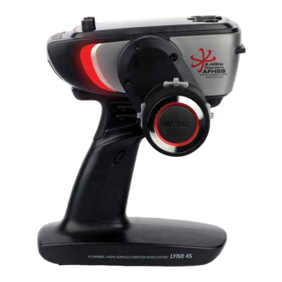
MANUAL: SECTION 1 Rubber Grip and Neck Strap (cont.) Receiver Hitec’s unique AFHSS (Adaptive Frequency Hopping Spread Spectrum) 2.4GHz system achieves new levels of outstanding performance and stability. Receiver Model Model Size Weight Stock Number AXION 2 1.26 x 0.87 x 0.43in (32 x 22.3 x 11mm) 0.25oz (7.0g) 27724 AXION 4... - Page 15 GPS Sensor (Built-in RX Type): A GPS speed sensor is factory-installed in the Proton 4 receiver. You can gauge your car speed on the Lynx 4S screen by using the Proton 4 receiver without any attachments. Range : 0~250km/H. Remember to use your...
-
Page 16: Receiver Installation
MANUAL: SECTION 1 Receiver Installation Receivers depend on sensitive technology. Do not expose your receiver to jarring vibrations, shock, or dust. Remember to take appropriate measures, like using sponge pads or thick, double-sided tape, to insulate your receiver against damaging forces. Do not bend or cut the ends of the 2.4GHz RX’s antenna wire. Please refer to the picture below for the proper installation method. -
Page 17: Receiver Connection Diagrams
Charging Charging Your Battery: The Lynx 4S radio set includes a NiMH 4-cell battery for your convenience. We recommend using Hitec’s overnight charger (CG-S82 220V/ CG-S85 110V) for your battery charging needs. Depending on the country of purchase, the CG-S82 (220V) / CG-S85 (110V) overnight chargers may not be included with your Lynx 4S package. - Page 18 2. A red light will glow to indicate active charging. 3. A green light will glow when the device is fully charged. If your Lynx 4S is turned on at the time you connect your overnight charger to the charging port, power to the radio will cut automatically.
-
Page 19: Main Display
MANUAL: SECTION 1 Main Display The main display shows general information regarding the operation of the Lynx 4S with your R/C models. The display is customizable by the user. 1. Model Name 11.Signal 10. [D1] Dual Rate Value 2. Multi-Screen 9. -
Page 20: Sub Menus
MANUAL: SECTION 1 Sub Menus MODEL PROGRAMING SET 1 [Pages 22 – 27] From this screen you can program the following items: Servo Reverse (R.E.V.), Endpoint Adjustments (E.P.A.), Brake Rate (ATL), Anti- Lock Brake (ABS), Steering Exponential (ST-EXP), Brake Exponential (BK- EXP), Throttle Exponential (TH-EXP), Steering Dual Rate (ST-D/R), Sub Trims (S-TRIM) and FAILSAFE. -
Page 21: Servo Reverse)
MANUAL: SECTION 2 REV (Servo Reverse) The REV function enables the user to adjust servo direction with changes to steering, throttle, and maneuvering the 3CH and 4CH models (settings are either clockwise or counterclockwise). 1. From the main screen, press the Main Dial button to enter the function menu. 2. -
Page 22: Brake Rate)
MANUAL: SECTION 2 ATL (Brake Rate) The ATL (Adjustable Travel Limiter) affects the braking response of your vehicle. A higher ATL value corresponds to a firmer braking response (a 100% value is the equivalent of slamming on your brakes), while a lower setting results in a more gradual stop. -
Page 23: St-Exp (Steering Exponential)
MANUAL: SECTION 2 ABS (Anti-Lock Brake cont.) Terms for ABS Setting: USE: Indicates the status (ON/OFF) of ABS [default: OFF] ON: The starting point of ABS operation when maneuvering the brake trigger [default: 30%] POW: The angle of the ABS brake power [default: 50%] DLY: Delays the time of ABS operation after setting the ABS starting point [default: 0ms] CYL: The recurring engagement time of the ABS brake [default: 100ms] STL: Steering mixing [default position: OFF]... -
Page 24: Bk-Exp (Brake Exponential)
MANUAL: SECTION 2 BK-EXP (Brake Exponential) Sets the servo operating conditions for brake direction. By adjusting these settings, you can create a more or less sensitive braking response for your vehicle. 1. Press the Main Dial button to view the function menu. 2. -
Page 25: St-D/R (Steering Dual Rate)
MANUAL: SECTION 2 ST-D/R (Steering Dual Rate) Users have the option of increasing or decreasing the servo operation angle with the dual rate adjusting dial [Default: 100]. 1. ST-D/R function is adjusted by the D1 Dial [under MIX mode 1]. 2. -
Page 26: Fail-Safe
MANUAL: SECTION 2 FAIL-SAFE Engaging the Fail-Safe option will move servos to a pre-saved position should you experience signal interference. As a safety precaution, it is highly recommended that the Fail-Safe mode is activated at all times. Hold Mode (HOLD): Servo will maintain its current position when the receiver is not capable of receiving signals. -
Page 27: Boost (Auto Boost)
MANUAL: SECTION 2 BOOST (Auto Boost) Quick start is not suitable under slippery road conditions. In conditions prone to tire spin, the BOOST function creates a smoother acceleration. BOOST Setting Display BOOST Function on Main Display USE: Indicates whether the BOOST function is ON or OFF [default: OFF]. MAX: sets the timer to automatically turn OFF the BOOST function [default: 5s]. -
Page 28: Th-Spd (Throttle Servo Speed)
MANUAL: SECTION 2 TH-SPD (Throttle Servo Speed) TH-SPD enables the user to set the momentum connected to the throttle servo or ESC. It allows for more stable driving control under different road conditions. 1. TH-SPD has four mode settings. 2. Press the Main Dial button to enter the function menu. 3. -
Page 29: Idl-Up (Idle Up/Down)
MANUAL: SECTION 2 IDL-UP (Idle Up/Down) The user has the option to adjust the engine’s idling parameters. You can prevent idling during vehicle refuel, or you can assign an idling period when you brake. 1. Press the Main Dial button to enter the function menu. 2. -
Page 30: Countdown Timer
MANUAL: SECTION 2 Timer (Race Timer cont.) Most of the switches can be assigned a TIMER START by switch section. Timers start or stop according to assigned switch. Please refer to Page 37 for more detail. Note You can view the current timer function on the main screen. Please refer to Page 52 for more details. Note Countdown Timer The DOWN TIMER option is handy when the user wants to check a certain time, like refuel time, repeatedly. -
Page 31: Lap Timer
MANUAL: SECTION 2 Lap Timer Allows the user to view details of each lap. To view all laps, go to the Lap List. MODE: Select the desired timer function. ALARM: Set the target alarm time. PRE: Set a pre-alarm notification. For example, setting a 35 second pre-alarm will sound a warning 35 seconds before your start time. -
Page 32: Switch (Switch Functions, Assignments & Settings)
MANUAL: SECTION 2 Lap List (Lap Time Listings cont.) 1. Press the Main Dial button to access the function menu. 2. Select ‘Timer’ under the SET 2/2 tab. 3. Check the Lap List by clicking the Main Dial over the highlighted option. The Lap List will be deleted upon restarting the Lap Timer or powering off. -
Page 33: Assignable Switch List
MANUAL: SECTION 2 Assignable Switch List Function Switch Type NOT LINK 4WS FS 4WS RS 4WS FR-N 4WS FR-S 4WS-S 4WS-3 TH-MIX AUX1 AUX2 TELEVOICE/U IDLE-UP/U ABS/U ST-EXP/U BK-EXP/U TH-EXP/U TIMER START TIMER CAPTURE TIMER R/START T-A ST T-B TH T-C AUX1 T-D AUX2 S-A ST... -
Page 34: Function Of Switch
MANUAL: SECTION 2 Function of Switch Function Description NOT LINK Clear Assigned function 4WS FS Change to Front Wheel Steer 4WS RS Change to Rear Wheel Steer 4WS FR-N Change to Front and Rear Steer 4WS FR-S Change to Front and Rear Steer (Same Phase) 4WS-S Change to Rear Steer or Back to 4WS-3 Status 4WS-3... -
Page 35: Dial (Radio Dial Functions & Settings)
MANUAL: SECTION 2 Dial (Radio Dial Functions & Settings) There are three dial positions that you may link to an R/C function of your choosing. FUNC: Type of Function DIR: Set to Normal /Reverse or ON/OFF. 1. Press the Main Dial button to enter the function menu. 2. -
Page 36: Dial Function
MANUAL: SECTION 2 Dial Function Function Switch Type NOT LINK AUX1 AUX2 T-A ST T-B TH T-C AUX1 T-D AUX2 S-A ST S-B TH S-C AUX1 S-D AUX2 ST-SPD + ST-SPD - TH-SPD1 TH-SPD2 TH-SPD3 ST-EXP BK-EXP TH-EXP T-A F-ST T-B F-TH T-C R-ST T-D R-TH... -
Page 37: Mix (Channel Mixing)
MANUAL: SECTION 2 Mix (Channel Mixing) The Lynx 4S provides 11 different mixing commands suitable to your R/C needs. 1. Press the Main Dial button to access the function menu. 2. Select ‘MIX’ under the SET 2/2 tab. 3. Select the type of Mixing command by using the Main Dial button. -
Page 38: 4Ws (4 Wheel Steering)
4WS (4 Wheel Steering) The Lynx 4S allows the user to control both front and rear steering either together or independently. You can control the 4WS system using TYPE 8 or TYPE 10 along with 11 different mix commands. You can assign control of the 4WS front/rear steering to a switch button if desired. -
Page 39: St-Adj (Steering Adjustments)
MANUAL: SECTION 3 ST-ADJ (Steering Adjustments) Use this function when a mechanical steering offset has occurred. Before After 1. Press the Main Dial button to access the function menu. 2. Select ‘ST-ADJ’ under the SYSTEM tab. 3. Turn the steering wheel left or right to adjust the corresponding values. A reading of “0 OK” represents Center. 4. -
Page 40: Rx-Bind (Receiver Binding)
RX-BIND “binds” the transmitter to the receiver so they operate as a unit pair. The Lynx 4S stores up to 30 models in its memory, which means users can bind up to 30 receivers to their Lynx 4S and control each one of them independently. -
Page 41: Rf-Scan (Radio Frequency Scanning)
5. The bind is complete when the LED on the transmitter flashes in color. Receiver Bind Process (same as AXION and PROTON): 1. Prepare the Lynx 4S for binding. 2. Press the ‘LINK’ button on the receiver and turn the power ON. -
Page 42: Servo (Servo Monitoring)
With this function, users can check the data output of the telemetry sensors on-screen and activate warnings to sound from the Lynx 4S speakers or earphone port. The telemetry function is only compatible with a PROTON 4 receiver. - Page 43 Temperature data gathered by the temperature sensor is displayed on-screen. Users can also set a warning level and spoken audio warning for this function. TMP: Temperature via TEMP sensor. SPEAK: Activate to issue an audio warning via the Lynx 4S speakers. USE: Issues a warning message when activated. WARNING: Set the desired warning level.
- Page 44 Data from the voltage sensor will be displayed on-screen. In this section, users are shown how to set a VOLT warning level and voice output. SPEAK: Activate to issue an audio warning via the Lynx 4S speakers. USE: Issues a warning message when activated.
- Page 45 Data from your GPS or RPM sensor will be displayed on-screen. In this section, users are shown how to set a SPEED warning level and voice output. SPEAK: Activate to issue an audio warning via the Lynx 4S speakers. SOURCE: Users have two options, GPS or RPM.
- Page 46 Data from the RPM sensor will be displayed on-screen. In this section, users are shown how to set an RPM warning level and voice output. SPEAK: Activate to issue an audio warning via the Lynx 4S speakers. SPEED: Set gear ratios so that the data from RPM sensor can be converted to the speed (Km/h).
-
Page 47: Management (Radio System Management Settings)
MANUAL: SECTION 3 Management (Radio System Management Settings) The Lynx 4S transmitter offers numerous customizable settings so that users can maximize comfort and convenience. LEFT HAND: The main screen turns 180 degrees for left- handed users. RST TIMER: Displays usage time on the main screen. -
Page 48: Telemetry (Telemetry Display)
MANUAL: SECTION 3 Telemetry (Telemetry Display) The main screen always displays certain information throughout the operation of your model. The information on-screen will change according to the data output from each sensor. [Scroll] Telemetry data appears when scrolling the main dial button up or down from the main screen. Note 1. -
Page 49: Vibration
Battery (Battery Type Settings) The Lynx 4S includes a Ni-MH battery and can be used with a Ni-CD, Li-Po, or Li-Fe battery. When the type of battery is changed, the Lynx 4S will automatically manage the new voltage system as shown below. -
Page 50: Name (Model Naming)
MANUAL: SECTION 4 Name (Model Naming) Users can create up to 12 model names. These names are shown on the main screen. 1. Press the Main Dial button to access the function menu. 2. Select ‘NAME’ under the MODEL tab. 3. -
Page 51: Copy (Model Copy)
MANUAL: SECTION 4 Copy (Model Copy) The model name and its corresponding settings can be duplicated under a new model. 1. Press the Main Dial button to access the function menu. 2. Select ‘COPY’ under the MODEL tab. 3. Select the model to be copied. When you copy a model, the settings of the original model are deleted. -
Page 52: Sd-Name (Sd Card Model Naming)
MANUAL: SECTION 5 SD-Name (SD Card Model Naming) 30 additional model names can be stored with the use of an SD card. 1. Press the Main Dial button to access the function menu. 2. Select ‘SD-NAME’ under the MODEL tab (SD-MODEL). 3. -
Page 53: Sd-Import (Sd Card Model Import)
MANUAL: SECTION 5 SD Import (SD Card Model Import) Model data that has been saved to the SD card can be imported to your transmitter. 1. Press the Main Dial button to access the function menu. 2. Select ‘SD-IMPORT’ under the MODEL tab (SD-MODEL). 3. -
Page 54: Voice (Voice Function)
Voice (Voice Function) The Lynx 4S can read sensor data outloud. Users can also assign a warning message by using a wave file. This function can be used with a micro SD card, the bidirectional audio output file offered by Hitec, a wave conversion program, or a wave file. -
Page 55: Warning & Error Messages
Note Warning & Error Messages Users should familiarize themselves with the various warning messages of the Lynx 4S in order to operate the system most effectively. NO INPUT: Alerts when the transmitter has not been used for a predetermined time to save battery. - Page 56 Phone: (858) 748 - 8440 E-mail: service@hitecrcd.com Web: www.hitecrcd.com...
Need help?
Do you have a question about the 4S and is the answer not in the manual?
Questions and answers