Table of Contents
Advertisement
Quick Links
Advertisement
Table of Contents

Related Manuals for Digital Monitoring Products XR550FC


Summary of Contents for Digital Monitoring Products XR550FC
- Page 1 XR150 /XR550 U S E R G U I D E...
- Page 2 Note: You may silence an alarm using both of the above methods on the Remote Fire Command Center as well. Copyright© 2013 Digital Monitoring Products, Inc. Information furnished by DMP is believed to be accurate and reliable. This information is subject to change without notice.
-
Page 3: Table Of Contents
XR150FC/XR550FC User’s Guide Table of Contents Section Page Section Page Emergency Evacuation Plans ........1 Zone Status ..............11 Draw a floorplan of your home or business ....... 1 System Status ............... 12 Develop escape routes ............. 1 System Test ..............13 Decide where to meet ............. - Page 4 Change User Profiles Browser ......... 28 Add User Codes Browser ..........28 Delete User Codes Browser ..........29 Change User Codes Browser .......... 29 Entering User Names ............. 30 Appendix C .............. 31 Common Keypad Displays ..........31 XR150FC/XR550FC User’s Guide...
-
Page 5: Emergency Evacuation Plans
The best way to survive a fire or other emergency is to get out early. The installation of a fire alarm system, with smoke and carbon monoxide detectors in each room, can greatly decrease your risk of loss or injury. Introduction XR150FC/XR550FC User’s Guide... -
Page 6: Introduction
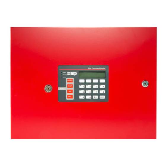
Fire Command Center The XR150FC/XR550FC comes with a built-in LCD display with a 20-key membrane keyboard called the Fire Command Center. The keyboard is mounted behind an opening in the red enclosure door. -
Page 7: The Fire Command Center
The Select keys status list. There are four keys under the display called the Select keys. They allow you to choose what to do by pressing the Select key under choices being shown in the display. Introduction XR150FC/XR550FC User’s Guide... -
Page 8: Using The Keypad
8 display. Press the COMMAND key to display areas 9 through 16. Press the COMMAND key again to display areas 17 through 25. Press the COMMAND key one more time to display areas 26 through 32. Note: Only areas pre-programmed at installation can display. XR150FC/XR550FC User’s Guide Introduction... -
Page 9: Four Function Keys
At SET VOLUME LEVEL, use the left Select key to lower the keypad volume. Use the right Select key to raise the volume. Model number The keypad model number, firmware version, and date display, but cannot be changed. Introduction XR150FC/XR550FC User’s Guide... -
Page 10: Special Fire Command Center Displays
A user has attempted a door access to an armed area to which they do not have arming and disarming authority. TRoUBLE There is a problem with a protection device or system component. This display is accompanied by a description of the problem. XR150FC/XR550FC User’s Guide Introduction... -
Page 11: Special Fire Command Center Tones
Press a Select key to silence. What to do when the trouble tone sounds You can silence the trouble tone by pressing any key. This only silences the keypad and does not correct the condition that originally caused the trouble. Introduction XR150FC/XR550FC User’s Guide... -
Page 12: Fire Command Center User Menu
Some features displayed on the User Menu are not necessary for model and version numbers. the XR150FC/XR550FC Addressable Fire Alarm Control Panel. Please SYSTEM TEST Tests the system siren, communication disregard these prompts and displays. Press the COMMAND key to to the central station, and backup skip any displays and prompts not discussed in this User Guide. -
Page 13: Alarm Silence
Key when the desired door is displayed. Make sure all smoke is cleared from around the smoke detector 4. Press Back Arrow return areas before performing a Sensor Reset to prevent the alarm from DOOR LOCK/UNLOCK? display. occurring again. System Setup XR150FC/XR550FC User’s Guide... -
Page 14: Door Access
2. Press COMMAND until DOOR ACCESS? displays. on. If you select a restricted output, the keypad displays 3. Press any Select key. The door strike relay turns on CANNOT TURN ON. momentarily. 4. The keypad returns to the Status List display. XR150FC/XR550FC User’s Guide System Setup... -
Page 15: Favorite
FAVORITE: -. For example, a zone status for zone 1 might be BACK DOOR - OKAY. 2. Enter a Favorite number from 1-20. Pressing COMMAND activates the Favorite. System Setup XR150FC/XR550FC User’s Guide... -
Page 16: System Status
These are followed by either OKAY or TRBL (trouble). If TRBL displays, call the service department for assistance. 4. The system then displays its firmware version (for example, VER_103_10/18/13), the panel model (MODEL XR550DN), and then exits the User Menu. XR150FC/XR550FC User’s Guide System Setup... -
Page 17: System Test
Press the COMMAND key to display the next failed zone. Note: During the Panic Zone Test, any zones that fail are not sent to the receiver unless pre-programmed at installation to be sent. System Setup XR150FC/XR550FC User’s Guide... -
Page 18: User Profiles
RE ARM DLY 0 – 720 Re-Arm Delay SEC LANGUAGE Preferred Language Always make sure that at least one administrator in your system has a profile with all authorities and all areas. XR150FC/XR550FC User’s Guide System Setup... - Page 19 Refer to Appendix B in this guide for a diagram showing you how to expire. Default is seven days from today. The system deletes use the Output Group browser and the Profile browsers. Temp users at 12:00 AM on the last date. System Setup XR150FC/XR550FC User’s Guide...
-
Page 20: User Codes
6 and 7 repeat. The User Profile assignment is automatically selected for the next user based on the previous user entered. This batch entry method speeds up user entry in large systems. XR150FC/XR550FC User’s Guide System Setup... - Page 21 USER NUMBER: -. This display allows you to change another user code. Press the Back Arrow key twice to exit the User Menu. Browser Feature Refer to Appendix B for diagrams showing you how to use the User Codes Add, Delete, and Change browsers. System Setup XR150FC/XR550FC User’s Guide...
-
Page 22: Extend Closing
Output allows you to choose an output to schedules set in the TIMES menu. Holiday dates allow you to enter special dates that activate Holiday Schedules that supersede all other schedules. Favorites allows you to activate a Z-Wave Favorite (1-20). XR150FC/XR550FC User’s Guide System Setup... -
Page 23: Setting Schedules
Enter all schedule times using a 12 hour clock. For example, name. To edit the name press any Select key to make to enter 6 AM you would enter a 0 + 6 + 0 + 0 and select AM. changes. Press COMMAND to proceed. System Setup XR150FC/XR550FC User’s Guide... - Page 24 6. The keypad returns to the TIMES AREAS DOOR display display – : AM PM. allowing you to enter additional programming. To exit the Enter a new time. user menu press the Back Arrow key. XR150FC/XR550FC User’s Guide System Setup...
-
Page 25: Setting Holiday Dates (Hol)
The display returns to the TIME DAY DATE display. when HOL schedules are used. For information on setting holiday Press the Back Arrow key to exit the User Menu. schedules for Area, Output, and Door, see Setting Holiday ABC Schedules. System Setup XR150FC/XR550FC User’s Guide... -
Page 26: Ambush Codes
2. The Fire Drill test automatically ends with ALARM SILENCE or system memory. Also, once the full 12,000 events are stored, any the programmed Bell Cutoff time. new event causes the oldest event to be cleared. See Appendix A for Display Events. XR150FC/XR550FC User’s Guide System Setup... -
Page 27: Appendix A
Appendix A About the Display Events Section 5. The keypad displays LAST DATE: 10/17. Press any Select key and enter a 4-digit ending date for the sort. Press COMMAND. This section of the User’s Guide shows the Display Events items. While in the Display Events function, use the COMMAND and Back 6. -
Page 28: Zone Event Displays
SVC - Service smoke detector 11:58P 10/ 17 central station at the date and LOW - Low battery MIS - Missing wireless transmitter AUTO RECALL time shown. Note: LOW and MIS are for wireless systems only. XR150FC/XR550FC User’s Guide Appendix A... - Page 29 System Monitor Event Displays This displays any problems with the system AC power, battery, or phone line(s), or any opening of a tampered panel box. 32-Character Display Description An AC failure occurred at 11:41 11:41A 10/ 17 AM. on Oct. 17. POWER System Monitor Event Types - There are 2 event types: TBL - Trouble...
-
Page 30: Zone Status Browser
-BYPAS = the zone is bypassed to enter another -BAD O = the zone is open -BAD O = the zone is open zone number. -BAD S = the zone is shorted -BAD S = the zone is shorted XR150FC/XR550FC User’s Guide Appendix B... -
Page 31: Outputs On/Off Browser
The next output group name displays. WINDOWS . . . OUTPUT: 127 ON OFF The display shows the door or output number. DOOR: 128 ON OFF Press any Select key/area and the output group FRONT OFFICE number displays. Appendix B XR150FC/XR550FC User’s Guide... -
Page 32: Change User Profiles Browser
When you complete changes The default user name appears. PROFILE 12 CHNGD USER 012 to the profile, press COMMAND. Press any SELECT key/area to clear this name. See the Entering User Names diagram in Appendix B. XR150FC/XR550FC User’s Guide Appendix B... -
Page 33: Delete User Codes Browser
Follow the prompts to complete the code change. and press COMMAND. You can also press any SELECT key/area here to clear a custom user name and use the USER 13 DELETED KATIE SMITH data entry keys to enter a new user name. Appendix B XR150FC/XR550FC User’s Guide... -
Page 34: Entering User Names
Entering User names XR150FC/XR550FC User’s Guide Appendix B... -
Page 35: Appendix C
The user must exit the area through the proper door. If FAILED TO EXIT attempted to re-enter an area from which they did not not possible, your system administrator should select the exit properly. Forgive option in the User Codes menu. XR150FC/XR550FC User’s Guide Appendix C... - Page 36 Function keys 5 Output Groups 27 Invalid Profile 6 Select Keys 3 Zone Status 26 Invalid Time 6 Status LEDs 3 Multi-lingual Option 4 Fire Command Center Displays 6 Service Required 7 Fire Command Center Tones Silenced 6 XR150FC/XR550FC User’s Guide Index...
- Page 37 Setting Output and Door Schedules Alarm LED 3 User Menu 2, 8 Power LED 3 User Menu Options Times 18 Trouble LED 3 Door Access 10 Select keys 3 Lockdown 9 User Options 5 Service Request 22 User Profiles 14 Index XR150FC/XR550FC User’s Guide...
- Page 38 Anti-Pass Back 15 Re-Arm Delay 15 Shift Schedules 15 Temporary Code 15 Zone Status Browser 26 Z-Wave 11, 18 XR150FC/XR550FC User’s Guide Index...
- Page 39 XR150FC/XR550FC User’s Guide...
- Page 40 LT-1298 © 2013 Digital Monitoring Products, Inc. 13525...
Need help?
Do you have a question about the XR550FC and is the answer not in the manual?
Questions and answers