Table of Contents
Advertisement
Quick Links
Advertisement
Table of Contents

Related Manuals for Marilyn DAR-01

Summary of Contents for Marilyn DAR-01
- Page 1 DAR-01 Rev. D User’s Manual Release Date 03/31/2015...
-
Page 3: Table Of Contents
Inputs with positive common ............................. 8 Outputs with negative common ............................9 Outputs with positive common ............................9 Serial to PC..................................10 Serial to Other Marilyn Systems Equipment ........................10 File Names ............................11 Configuration File ..........................12 INI file overview .................................. 12 [StartUp] Section ................................ - Page 4 2015, Marilyn Systems, llc.
-
Page 5: Introduction
Marilyn Systems will however cover reasonable return shipping charges for products repaired or replaced under the conditions of this warranty. All products manufactured by others and sold as such by Marilyn Systems shall be governed by the terms of said manufacturer’s warranty. -
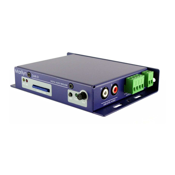
Page 6: Device Overview
A solid-state relay output provides devices status. Out of the box, the DAR-01 can be surface or edge mounted. An optional DIN-rail mount kit is available for standardized integration into industrial panels. A card-guard kit is also available to prevent card removal. -
Page 7: Device Layout
All sound files and configuration information are stored a SD or SDHC flash memory card. The card is inserted by gently pushing it into the socket, with the contacts down and towards the DAR-01, until a “click” is heard. To remove the card, push it in slightly until a “click” is heard. The card is now unlocked and will be ejected from the socket. -
Page 8: Left Panel
SERIAL Connector RS-232 port brought out on an EIA-561 compatible RJ-45 jack. See configuration file section for serial port operating parameters. Terminal Function Signal Ground DAR-01 Rx DAR-01 Tx Reserved Pin-out (cable-end, connector front) Table 4 2015, Marilyn Systems, llc. -
Page 9: Right Panel
Channel A (left) positive terminal Channel B (right) negative terminal Channel B (right) positive terminal Table 5 If you are upgrading from a rev. b or rev. c DAR-01, please notice that the amplifier output pin-outs have changed. 24VDC IN Connector The DAR-01 can operate on a little as 12VDC however for optimal amplifier performance, 24VDC should be provided. -
Page 10: Power
Power Wiring Example Figure 4 – Power wiring example 2015, Marilyn Systems, llc. -
Page 11: Wiring Examples
Speaker Wiring Examples Figure 5 – Stereo speaker wiring example Figure 6 – Mono speaker wiring example (amp paralleled) 2015, Marilyn Systems, llc. -
Page 12: Inputs With Negative Common
Input Wiring Examples Figure 7 – Inputs with negative common wiring example Figure 8 – Inputs with positive common wiring example 2015, Marilyn Systems, llc. -
Page 13: Outputs With Negative Common
Output Wiring Examples Figure 9 – Output with negative common wiring example Figure 10 – Output with positive common wiring example 2015, Marilyn Systems, llc. -
Page 14: Serial To Pc
Serial Port Wiring Examples Figure 11 – DAR-01 to computer RS-232 serial port wiring Figure 12 – DAR-01 to other EIA-561 serial device wiring 2015, Marilyn Systems, llc. -
Page 15: File Names
Is not. Filename.Ext Audio files on the DAR-01 must be named in a very specific format so that the unit can find and access them. The first 5 characters of the filename are always ‘SOUND’ followed by a 3-digit decimal number representing the track number. -
Page 16: Configuration File
This file must be named CONFIG.TXT so that the player can find it on startup. The configuration file for the DAR-01 is based on the standard INI file format. Each operating parameter of the DAR-01 consists of a name and value separated by an equal sign (=). name = value Parameters are grouped by section. -
Page 17: [Startup] Section
[Startup] section The Startup section defines the behavior of the DAR-01 immediately after power-up or card insertion. Startup section parameters: Action - Describes what the player should do when powered up. Value Function DoNothing Take no action (Default) Play Play the specified track(s). -
Page 18: [Audio] Section
; In this example, we disable the amplifier. Note that this is not ; necessary as parameters assigned to their default values do not ; need to be specified in the configuration file. [Audio] AmpEnabled=No AmpBoost= No 2015, Marilyn Systems, llc. -
Page 19: [Serial] Section
SerialAddress- Defines the serial communications address this device will respond to. This number must be in the range of 1 to 254 and if not defined, the DAR-01 will respond to all serial messages. This parameter will be ignored if the serial port is disabled. Note that this not currently used but left in for compatibility with previous models. -
Page 20: [Input] Section
Defines how the device will respond to the optically-isolated inputs. Inputs section parameters: Mode – Sets the general operating mode of the inputs. Value Function Individual The function of each input can be independently defined (default) Table 12 ; Inputs operate individually [Inputs] Mode=Individual 2015, Marilyn Systems, llc. -
Page 21: [Inputxmake] Section
10mS increments (10= 1second). If zero (default value), then no fade will occur. Fading is disabled by default if volume is undefined. Fading is still active regardless of the defined action. Maximum value is 255 (25.5 seconds). 2015, Marilyn Systems, llc. -
Page 22: [Inputxbreak] Section
10mS increments (10= 1second). If zero (default value), then no fade will occur. Fading is disabled by default if volume is undefined. Fading is still active regardless of the defined action. Maximum value is 255 (25.5 seconds). 2015, Marilyn Systems, llc. -
Page 23: [Buttonmake] Section
10mS increments (10= 1second). If zero (default value), then no fade will occur. Fading is disabled by default if volume is undefined. Fading is still active regardless of the defined action. Maximum value is 255 (25.5 seconds). 2015, Marilyn Systems, llc. -
Page 24: [Buttonpress] Section
10mS increments (10= 1second). If zero (default value), then no fade will occur. Fading is disabled by default if volume is undefined. Fading is still active regardless of the defined action. Maximum value is 255 (25.5 seconds). 2015, Marilyn Systems, llc. -
Page 25: [Buttonbreak] Section
10mS increments (10= 1second). If zero (default value), then no fade will occur. Fading is disabled by default if volume is undefined. Fading is still active regardless of the defined action. Maximum value is 255 (25.5 seconds). 2015, Marilyn Systems, llc. -
Page 26: [Buttonrelease] Section
10mS increments (10= 1second). If zero (default value), then no fade will occur. Fading is disabled by default if volume is undefined. Fading is still active regardless of the defined action. Maximum value is 255 (25.5 seconds). 2015, Marilyn Systems, llc. -
Page 27: [Userpot] Section
Value Function The volume control is enabled (default) The volume control is disabled and the DAR-01 volume level is fixed at the defined Max level Table 21 Min - Sets the minimum volume. Defined as 0 to 100% of full scale. 0 is default. -
Page 28: [Userled] Section
Mode - Status output operating mode. Value Function Disabled The status output does nothing Playing The status output is active while a track is playing (default) Stopped The status output is active while the unit is stopped Table 23 2015, Marilyn Systems, llc. -
Page 29: Buttonxmake, Buttonxbreak, Volumecontrol, Playled, And Statusoutput Examples
Min= 50 Max= 75 ;********** ; Play LED will light when the unit is playing audio [PlayLed] Enabled= Yes ;********** ; The status output relay contacts will close when audio playback is ; stopped. [StatusOutput] Mode= Stopped 2015, Marilyn Systems, llc. -
Page 30: Configuration File Application Examples
CONFIG.TXT application by saving a and editing as needed. File: CONFIG.001 ; Example DAR-01 Configuration File ; Written by: JLP ; -Tracks 12 through 27 will loop endlessly on startup. ; -Internal amplifier is disabled. ; -Volume control controls volume from 0 to 100 percent. -
Page 31: Config.002
File: CONFIG.002 ; Example DAR-01 Configuration File ; Written by: JLP ; -Tracks 12 through 27 will be looped endlessly in BGM mode. each time the BGM loop is interrupted, the volume will take 2 to ramp up to the set level of 80 percent. -
Page 32: Config.003
File: CONFIG.003 ; Example DAR-01 Configuration File ; Written by: JLP ; -Tracks 12 through 27 will be looped endlessly in BGM mode. each time the BGM loop is interrupted, the volume will take 5 to ramp up to the set level of 80 percent. -
Page 33: Config.004
File: CONFIG.004 ; Example DAR-01 Configuration File ; Written by: JLP ; -Track 1 will play each time input 1 is made. ; -Internal amplifier is enabled. Amp boost is disabled by default ; -User Level pot controls volume from 0 to 100 percent. -
Page 34: Ascii Serial Protocol
PL02 – Play track 2 on the DAR-01 – Stop the DAR-01 – Loop tracks 1 through 10 in BGM mode. Volume = 100 and fade-time = 2 BG1,10,100,20 seconds. 03PL04 – Play track 4 on the DAR-01 with address 3. 2015, Marilyn Systems, llc. -
Page 35: Firmware Upgrade
Do not rename the file or change any file attributes. 2. With the DAR-01 powered off, insert the memory card. 3. Power the DAR-01. Both LEDs will begin to flash. Be patient as the upgrade process can take up to a minute. -
Page 36: Techical Specification
DAR-01 Technical Specification Audio • Plays MP3 files at rates up to 320Kb/s and 16-bit WAV files at up to 44.1KHz • Unbalanced 2VRMS stereo line-out • Class-D stereo amplifier delivers 40Watts-per-channel into a 4 to 8 ohm load at 24VDC Storage •... -
Page 37: Mechanical Drawings
Mechanical Drawings Figure 13 –Mechanical drawing 2015, Marilyn Systems, llc.
Need help?
Do you have a question about the DAR-01 and is the answer not in the manual?
Questions and answers