Advertisement
Quick Links
Download this manual
See also:
Assembly Manual
Advertisement

Subscribe to Our Youtube Channel
Related Manuals for Horizon Fitness H-CELL 2.0


Summary of Contents for Horizon Fitness H-CELL 2.0
-
Page 1: Assembly Guide
H-CELL Assembly guide* H CELL H-CELL 21st century power system for 1/10 RC hobby racing H-cell 2.0_AG_V2.9_EN *standard integration based on using TRF416/416X/417 chassis from TAMIYA... -
Page 2: Safety Information
SAFETY INFORMATION please read before proceeding to assembly Equipped with high performance running battery and motor, R/C car models are capable of speeds of over 50km/h. Operating R/C models in improper areas may result in accidents causing injury or property damage. d l i i lt i Follow the instructions outlined below to fully enjoy operating your R/C car. -
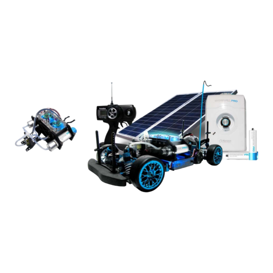
Page 3: Parts List
H-CELL Parts list A. Fuel cell unit B. Pressure regulators C. Hydrogen cartridges D. Electronic Valve Support E. Electronic Control Box F. Aluminum support plate G. Silicon rubber tubing H. Four-port connector Fasteners Spanner K. Screw driver L. Aluminum plate connectors M. - Page 4 Recommended RC vehicle* parts list (not included in the H-Cell 2.0 kit) Item Supplier Ref. number Chassis TAMIYA TRF416/416X/417 Speed controller TAMIYA TBLE -01 Servo motor Futaba BLS551 RC transmitter/receiver Futaba Lithium Battery 2800-4000mAH/7.4V Motor TAMIYA 3.5T brushless Motor heat sink**...
- Page 5 H-CELL Standard Integration Design Pressure Regulator 30W PEM Fuel Cell Stack Electronic Controller Twin Air-Supply (O Twin Air Supply (O ) Fans ) Fans Hydrogen Cartridge Fuel Cell On/Off Switch Aluminum support plate Heat Diffusion plate RC transmitter/receiver Speed controller Page 5 of 43 *standard integration based on using TRF416/416X/417 chassis from TAMIYA...
- Page 6 Step 30: *Although we recommend TRF416/416X/417 from TAMIYA and our aluminum support plate is designed around this model, the H-cell 2.0 kit could be adapted to various RC vehicles and boats with some additional engineering. Page 6 of 43 **We recommend Futaba BLS 551 due to its smaller size.
- Page 7 STEP 2: Use black double-sided tape to attach the antenna’s signal receiver (Q)* to the chassis (N). *See recommended parts list (Horizon recommends using FUTABA 2PL for this assembly) Page 7 of 43...
- Page 8 STEP 3: Use black double-sided tape to attach the speed controller* (O) to the chassis (N). *See recommended parts list (Horizon recommends the TAMIYA TBLE-01 speed controller for this assembly) Page 8 of 43...
- Page 9 STEP 4: Use black double-sided tape to attach the speed controller (O)* switch to the chassis (N). Paste speed controller On/Off switch onto outer side of speed controller (O) onto outer side of speed controller (O) Page 9 of 43...
- Page 10 STEP 5: Insert the red plug and grey plug from speed controller (O) into socket “B” of signal received (Q) and black plug from the servo motor (P) into socket “1”. Place red plug from speed controller (O) into socket “B” Place black plug from servo motor (P) into socket “1”...
- Page 11 STEP 6: Insert the grey plug from speed controller (O) into socket “2” of the antenna’s signal receiver (Q). Use a plastic tie (part M) to attach the cable to the chassis (N) together so wire doesn’t hang from chassis. Make sure all the connections are correct.
- Page 12 STEP 7: Position the motor heat sink (T) onto the motor (S). Connect speed controller to the motor as below. Ensure the cables are connected correctly. y Page 12 of 43...
- Page 13 STEP 8: Use black double-sided tape to attach the (fully charged) battery (R)* to the chassis (N) as below. *See recommended parts See recommended parts list, be sure to charge the battery before starting this step. list, be sure to charge the battery before starting this step. Page 13 of 43...
- Page 14 STEP 9: Assembling the hydrogen fuel cell system A. Disconnect one end of the tube that connects both gas connection points on the fuel cell (A) as shown below. connection points Disconnect the tubing from only one of the connection points Page 14 of 43...
- Page 15 STEP 9: Assembling the hydrogen fuel cell system B. Connect a new tubing (G) to the remaining free gas connection point on the fuel cell (A) as shown below. Page 15 of 43...
- Page 16 STEP 9: Assembling the hydrogen fuel cell system C. Connect each tube to the white plastic connector located on the electronic input and output valves as below. Connect the filter(M2) between the fuel cell stack output and the output valve. Make sure the small end of the filter is connected to the fuel cell stack output tube.
- Page 17 STEP 9: Assembling the hydrogen fuel cell system D Turn the fuel cell (A) upside down and place the aluminum plate (F) exactly as shown below D. Turn the fuel cell (A) upside down and place the aluminum plate (F) exactly as shown below. Use the spanner (K) to connect the plate to the fuel cell tightly.
- Page 18 STEP 9: Assembling the hydrogen fuel cell system E. Use plate connector (L) and screw/washer assembly to connect aluminum plate (F) to the fuel cell (A) as shown below: (I)(4) (I)(5) (I)(3) Page 18 of 43...
- Page 19 STEP 9: Assembling the hydrogen fuel cell system F. Secure the aluminum plate to the fuel cell. You should obtain the assembly below: (I)(4) (I)(5) (I)(5) (I)(2) (I)(1) Page 19 of 43...
- Page 20 STEP 9: Assembling the hydrogen fuel cell system Turn your fuel cell / aluminum support assembly upside down and use your spanner to tighten the nut to the assembly. Page 20 of 43...
- Page 21 STEP 9: Assembling the hydrogen fuel cell system Turn your assembly upside down and position the valve holder (D) under the aluminum plate (F) exactly as below. Use the spanner and two screws (I)(1) to connect the valve holder (D) to the aluminum plate (F). Note: Do not tighten the screws yet as you will need to implant the electronic valves into the construction (next step).
- Page 22 STEP 9: Assembling the hydrogen fuel cell system Position the fuel cell’s ( A) OUTPUT VALVE (see stickers on the valves) on the aluminum plate (F) as below, with the INPUT VALVE positioned below it, into the valve support unit (D). Now tighten the screws that connect the valve support unit (D) to the aluminum plate.
- Page 23 STEP 10: Assembling the hydrogen fuel cell system: COMPLETED! Page 23 of 43...
- Page 24 STEP 11: Connecting the HYDROSTIK hydrogen cartridges to the fuel cell system assembly A. Connect four silicon rubber tubes (G) to the four-port connector (H) to obtain the assembly below. Page 24 of 43...
- Page 25 STEP 11: Connecting the HYDROSTIK hydrogen cartridges to the fuel cell system assembly B. Connect two of the four tubes in the previous assembly to the two pressure regulators (B) as shown below. Page 25 of 43...
- Page 26 STEP 11: Connecting the HYDROSTIK hydrogen cartridges to the fuel cell system assembly C. Connect one remaining tube to the input valve (located on top) of the fuel cell system assembly. Page 26 of 43...
- Page 27 STEP 11: Connecting the HYDROSTIK hydrogen cartridges to the fuel cell system assembly D. Connect the (fully charged) HYDROSTIK PRO cartridges (C) to both pressure regulators (B). Make sure to screw-in the canisters tightly when in use and be sure to disconnect them after use. Note: 1.
- Page 28 STEP 11: Connecting the HYDROSTIK hydrogen cartridges to the fuel cell system assembly E. Position both HYDROSTIK PRO cartridges (C) onto both canister support units on the system. Use the screw driver to tighten. Note: Before position both HYDROSTIK PRO cartridges (C) onto both canister support units, place a piece of silicon sheet (M1) on the support unit to protect the canister.
- Page 29 STEP 12: Connecting the electronic control box to the fuel cell system assembly A. Remove cover from the electronic control box (E). cover System controller LED Indicator System controller LED Indicator Starting up Period Controller LED Indicator Status Red LED flashes & Green LED off Lithium battery voltage <6V Red LED lights &...
- Page 30 STEP 12: Connecting the electronic control box to the fuel cell system assembly B. Turn the fuel cell system assembly upside down, and place the electronic control box COVER on the aluminum support plate, aligning the screw holes as below. Use the spanner and two screws (I)(1) to connect the box cover to the aluminum support plate (F).
-
Page 31: Pressure Switch
STEP 12: Connecting the electronic control box to the fuel cell system assembly C Place the electronic box (E) over its cover and press down to connect to the rest of the fuel cell system assembly C. Place the electronic box (E) over its cover and press down to connect to the rest of the fuel cell system assembly. Make sure the pressure switch is connected to the four connecting port. - Page 32 STEP 13: Connecting the fuel cell system to the modified vehicle chassis (see step 1) A. Position the fuel cell system assembly onto the chassis as below, carefully aligning the screw connection points. the spanner and screws (I)(5) to connect the support plate to the chassis. Page 32 of 43...
- Page 33 STEP 13: Connecting the fuel cell system to the modified vehicle chassis (see step 1) B. Connect back section of the aluminum support plate (F) to the chassis (N) as below. (I)(3,4) Page 33 of 43...
- Page 34 STEP 13: Connecting the fuel cell system to the modified vehicle chassis (see step 1) C. Connect front section of the aluminum support plate (F) to the chassis (N) as below. (I)(3,4) Page 34 of 43...
-
Page 35: Electronic Connections
STEP 14: Electronic connections A. Connect the fuel cell (A) to electronic control box (E). Page 35 of 43... - Page 36 STEP 14: Electronic connections B. Connect the electronic controller (E) to the motor (R). Page 36 of 43...
- Page 37 STEP 14: Electronic connections C. Follow the steps below to connect the electronic controller to the Lithium Battery. Page 37 of 43...
-
Page 38: Antenna Connections
STEP 15: Antenna connections Push the antenna wire through the antenna tube. Insert the tube into the antenna base as below. Page 38 of 43... - Page 39 CONGRATULATIONS! Your hydrogen fuel cell hybrid RC car is now ready to go! Page 39 of 43...
- Page 40 STEP Turning the system “on” Turn the gas switch to the “ON” position (A). The fans on the H-cell activate and the blue LED lights turn on. Turn on the receiver’s switch and activate the remote control unit. Use the RC unit to steer the car. Page 40 of 43...
- Page 41 Additional recommendations (please read carefully): 1.The electronic valves have input and output connections. HYDROSTIK PRO cartridges should only be connected to the input valve. If connected differently, the system will not function properly. 2. To avoid failure of the control box which can be caused by battery power leakage, please disconnect the lithium battery from the control box after use.
-
Page 42: Troubleshooting
Troubleshooting Troubleshooting 1.After turning on the electronic control box switch, the red light in the control box flashes, while the green light disappears. This indicates the Li-battery is drained and needs to be charged. Solution: 1) Charge the battery. 2) Check the battery connection to the fuel cell system and reconnect it again. 2.After turning on the electronic control box switch, the red light in the control box flashes, while the green light Is on. - Page 43 Troubleshooting (continued) 5. While the car is running, the red light inside the electronic control box turns on and the green light turns off. This is a warning sign that the fuel cell voltage is low. Solution: 1) Canister is empty, use fully charged canisters. 2) Check the connection between the canister and the pressure regulator.
Need help?
Do you have a question about the H-CELL 2.0 and is the answer not in the manual?
Questions and answers