Table of Contents
Advertisement
Available languages
Available languages
Quick Links
Advertisement
Table of Contents

Related Manuals for DAS DSP-48

Summary of Contents for DAS DSP-48
- Page 2 ATTENTION! The DSP-48 fits into a standard 19" rack unit of space (1 3/4"). Allow at least an additional 4" depth for the connectors on the back panel. Be sure that there is enough air space around the unit for cooling and ventilation.
- Page 3 CARACTERíSTICAS Procesador digital de señal de 24 bits. 4 entradas/ 8 salidas con varios tipos de crossover para dar gran flexibilidad de configuración. Filtros de tipo Butterworth, Linkwitz-Riley o Bessel, con pendientes de cruce de 12 dB, 18 dB, 24 dB y 48 dB por octava. 6 puntos de EQ en cada entrada y 4 puntos de EQ en cada salida.
-
Page 4: Panel Frontal
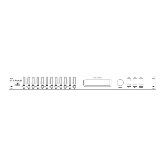
PANEL FRONTAL 10 11 12 1 . Barra de leds de 7 segmentos para indicador nivel de entrada. 2 . Barra de leds de 7 segmentos para indicador nivel de salida 。 3 . Pantalla LCD indicadora de todos los parámetros y funciones Pulsador / giratorio (PARAMETER) para acceso a menú... -
Page 5: Panel Trasero
PANEL TRASERO Alimentación. Conector USB para control vía PC. Interface RS485. Ocho conectores XLR macho para salida de señal. Cuatro conectores XLR hembra para entrada de señal. - Page 6 OPERACIONES 1.Ajuste de parámetros en el canal de entrada. INPUT GAIN /Ganancia de entrada. IN:A El rango de ganancia es de -40 dB a +12dB. En pasos de 0.1dB. Gain = 0.0dB Use el botón PARAMETER, para cambiar el valor preestablecido. El botón giratorio PARAMETER cambia el valor en pasos de 0.1 dB.
- Page 7 OPERACIONES COPY INPUT DATA / Copiar datos de entrada Copy Input A Con el botón giratorio PARAMETER seleccionamos el canal en el que to Input: B queremos copiar los ajustes. Pulse NEXT para acceder al sub-menú input gain. Pulse PREV para acceder al sub-menú input EQ. Presione PARAMETER para cambiar de canal.
- Page 8 OPERA ON Mediante botón giratorio PARAMETER podemos ajustar estas opciones. Pulse NEXT para entrar en el sub-menú output high-pass. Pulse PREV para entrar en el sub-menú output delay. Los pulsadores cambian las opciones: ganancia, fase, fuente de entrada y otras opciones. Pulse el botón giratorio PARAMETER para acceder al siguiente canal.
- Page 9 OPERA ION Mediante el botón giratorio PARAMETER ajustaremos el valor deseado. Pulse NEXT para acceder al sub-menú copy output data. Pulse PREV para acceder al sub-menú output low-pass. Pulse para ajustar opciones del limitador, umbral, ratio, tiempo de ataque y tiempo de relajación. Presione el botón giratorio PARAMETER para acceder al siguiente canal.
- Page 10 OPERA ION 4.2 Loading program / cargar programa Program Load a program Pulse SAVE/ENTER para acceder a la operación de cargar un programa. LOAD PROGRAM: 1 4X2-WAYCrossover Gire el botón PARAMETER para cambiar el nombre del programa, presione SAVE/ENTER para cargar un programa. LOADING PROGRAM 4X2-WAYCrossover 4.3 Storing program / almacenar programa...
-
Page 11: Set Password
OPERA ION 5. Menú de seguridad 5.1 Bloqueo Hay cuatro tipos de bloqueo: MAIN MENU:.*..SECURITY 1: Modify / Modificar Pulse SAVE/ENTER para acceder al Los parámetros pueden verse pero no cambiarse. Mute activo. sub-menú de seguridad. & 2: Modify View / Modificar y ver Lock Type Los parámetros no pueden verse o cambiarse. - Page 12 OPERA ION 6. Copiar Programa Copiar programa entre todas las unidades.La unidad principal (master) envia una copia del programa a una unidad secundaria (slave). Para que la unidad principal envie la copia del programa, se tiene que conectar el interfaz de salida (RS485 OUT) de la unidad principal y el interfaz de entrada (RS485 IN) de la unidad secundaria mediante un cable de red.
- Page 13 OPERA ION APPENDIX: Preset mode input source and crossover parameter sheet Preset name Output Input source High-pass frequency Low-pass frequency 1:4x2-WAYCrossover OUT1 19.7Hz 1000Hz OUT2 1000Hz OUT3 19.7Hz 1000Hz OUT4 1000Hz OUT5 19.7Hz 1000Hz OUT6 1000Hz OUT7 19.7Hz 1000Hz OUT8 1000Hz 2:2x3-WAY+2 Aux OUT1...
- Page 14 OPERACIONES Preset name Output Input source High-pass frequency Low-pass frequency 8:LCR + mono Sub OUT1 99.2Hz OUT2 99.2Hz OUT3 99.2Hz OUT4 99.2Hz OUT5 99.2Hz OUT6 99.2Hz OUT7 99.2Hz OUT8 99.2Hz 9:4x4 Processor OUT1 OUT2 OUT3 OUT4 OUT5 OUT6 OUT7 OUT8 10:Muted all OUT1 OUT2...
- Page 15 FEATURES 24-bit Dual DSP technology high funtional AKM AD AK5392. 4 Inputs / 8 Outputs multi-kinds of crossover mode for flexible configuration. Crossover slope of12dB,18dB,24dB or 48dB per octave filter type Butterworth, Linkwitz-Riley or Bessel 6 bands EQ every input, 4 bands EQ every output, Parametric, L-Shelf H-Shelf. Parametric EQ: Full bandwidth, 1/64 to 4.0 octave range.
-
Page 16: Front Panel
FRONT PANEL 10 11 12 1 . Seven band input meter. 2 . Seven band output meter 2X20 character LCD to indicate all kinds of parameter. 4 . PARAMETER with PUSH PUSH Key to switch the main menu. Rotate PARAMETER to adjust parameter value, password character and program name and so on. 5 . -
Page 17: Rear Panel
REAR PANEL Power Jack USB interface, PC control interface. RS485 i nterface Eight channel XLR output terminal Four channel XLR input terminal... -
Page 18: Operation
OPERATION 1.Input channel parameter setting INPUT GAIN Gain range is-40dB~12dB step is 0.1dB IN:A Use PARA METER key to change parameter value. Gain = 0.0dB When use PARAMETER to change parameter value, step is 0.1dB. when use key to change parameter value, step is 5.0dB On the front panel there is input MUTE key to mute quickly. - Page 19 OPERATION COPY INPUT DATA Rotate PARAMETER to change target input channel number. Copy Input A Press <NEXT> to enter into the input gain sub -menu. to Input: B Press <PREV> to enter into the-input EQ sub- menu. Press the PARAMETER to switch the channel. 2.Output channel parameter setting OUTPUT GAIN Op1 Gain...
- Page 20 OPERATION Press NEXT key to enter output high-pass sub-menu. Press PREV key to enter output delay sub-menu. Press key to switch gain, phase and input source and so on option. Arrow indicate current option. Press PARAMETER key to switch channel. OUTPUT HIGH-PASS FILTER Filter frequency range is 19.7Hz~21.9kHz.
- Page 21 OPERATION Press PREV key to enter output low pass sub-menu. Press key to switch limiter threshold, limiter ratio, attack time and release time and so on option. Arrow indicate current option. Press PARAMETER key to switch channel. COPY OUTPUT DATA Rotate PARAMETER to change target output channel number.
- Page 22 OPERATION 4.2 Loading Program Program Load a program Press SAVE/ENTER key to enter the operation of load a program LOAD PROGRAM: 1 4X2-WAYCrossover Rotate PARAMETER to change program name, press SAVE/ENTER key to load program LOADING PROGRAM 4X2-WAYCrossover 4.3 Storing program It may store all parameters of input gain, input delay , input EQ, output gain, output delay, output EQ, output limit and output phase into the program, convenient for the unit to debug.
-
Page 23: Security Menu
OPERATION 5. Security Menu 5.1 Adding the lock Four lock types: 1:Modify The parameters can be viewed but not MAIN MENU:.*..change. Mute is active. SECURITY 2:Modify&View The parameters cannot be viewed or changed. Mute is active. Press SAVE/E NTER key to enter security sub-menu. - Page 24 OPERATION 5. Security Menu 5.1 Adding the lock Four lock types: 1:Modify The parameters can be viewed but not MAIN MENU:.*..change. Mute is active. SECURITY 2:Modify&View The parameters cannot be viewed or changed. Mute is active. Press SAVE/E NTER key to enter security sub-menu.
- Page 25 OPERATION APPENDIX: Preset mode input source and crossover parameter sheet Preset name Output Input source High-pass frequency Low-pass frequency 1:4x2-WAYCrossover OUT1 19.7Hz 1000Hz OUT2 1000Hz OUT3 19.7Hz 1000Hz OUT4 1000Hz OUT5 19.7Hz 1000Hz OUT6 1000Hz OUT7 19.7Hz 1000Hz OUT8 1000Hz 2:2x3-WAY+2 Aux OUT1 19.7Hz...
- Page 26 OPERATION Preset name Output Input source High-pass frequency Low-pass frequency 8:LCR + mono Sub OUT1 99.2Hz OUT2 99.2Hz OUT3 99.2Hz OUT4 99.2Hz OUT5 99.2Hz OUT6 99.2Hz OUT7 99.2Hz OUT8 99.2Hz 9:4x4 Processor OUT1 OUT2 OUT3 OUT4 OUT5 OUT6 OUT7 OUT8 10:Muted all OUT1 OUT2...
- Page 27 SPECIFICATION / ESPECIFICACIONES Ω Input impedance Maxium input electrical level 4Vrms Input CMRR 55dB Input XLR DY-08 Sampling rate 48KHz Ω Output impedance Maxium output electrical level 2Vrms Output XLR DY-09 Input gain -40.0dB~12.0dB,step:0.1dB Output gain -40.0dB~12.0dB,step:0.1dB Input delay 682.52ms, step: 21us 。...
Need help?
Do you have a question about the DSP-48 and is the answer not in the manual?
Questions and answers