
Summary of Contents for ADT A-O14QCP2
-
Page 1: Instruction Manual
INSTRUCTION MANUAL A-O14QCP2 14” COLOR QUAD OBSERVATION MONITOR Please read this manual thoroughly before use, and keep it handy for future reference. - Page 2 ISSUE 1 – MARCH 2002 LIMITATION OF LIABILITY THE INFORMATION IN THIS PUBLICATION IS BELIEVED TO BE ACCURATE IN ALL RESPECTS, HOWEVER, WE CANNOT ASSUME RESPONSIBILITY FOR ANY CONSEQUENCES RESULTING FROM THE USE THEREOF. THE INFORMATION CONTAINED HEREIN IS SUBJECT TO CHANGE WITHOUT NOTICE. REVISIONS OR NEW EDITIONS TO THIS PUBLICATION MAY BE ISSUED TO INCORPORATE SUCH CHANGES...
-
Page 3: Fcc Compliance Statement
FCC COMPLIANCE STATEMENT INFORMATION TO THE USER: THIS EQUIPMENT HAS BEEN TESTED AND FOUND TO COMPLY WITH THE LIMITS FOR A CLASS B DIGITAL DEVICE, PURSUANT TO PART 15 OF THE FCC RULES. THESE LIMITS ARE DESIGNED TO PROVIDE REASONABLE PROTECTION AGAINST HARMFUL INTERFERENCE IN A RESIDENTIAL INSTALLATION. -
Page 4: Warnings And Cautions
WARNINGS AND CAUTIONS TO REDUCE THE RISK OF FIRE OR ELECTRIC SHOCK, DO NOT EXPOSE THIS PRODUCT TO RAIN OR MOISTURE. DO NOT INSERT ANY METALLIC OBJECTS THROUGH THE VENTILATION GRILLS OR OTHER OPENINGS ON THE EQUIPMENT. CAUTION EXPLANATION OF GRAPHICAL SYMBOLS The lightning flash with arrowhead symbol, within an equilateral triangle, is intended to alert the user to the presence of uninsulated “dangerous voltage”... -
Page 5: Important Safeguards
IMPORTANT SAFEGUARDS 10. LIGHTNING READ AND RETAIN INSTRUCTIONS Read the instruction manual before operating the For protection of the equipment during a lightning storm equipment. Retain the manual for future reference. or when it is left unattended and unused for long periods of time, unplug the unit from the wall outlet. - Page 6 {This page intentionally left blank.}...
-
Page 7: Table Of Contents
TABLE OF CONTENTS FEATURES..........................1 MONITOR SETTINGS / CONTROLS..................2 FRONT PANEL CONTROLS ....................2 Microphone ......................2 Volume......................... 2 Tint ........................2 Color ........................3 TALK Button / LED ....................3 MODE Button / LED ..................... 3 SEQ Button / LED ....................3 Camera Buttons (1-4) / Arrow Buttons.............. - Page 8 VCR Playback........................ 15 VCR ZOOM Function..................... 15 FREEZE DISPLAY....................... 15 ALARMING FUNCTIONS ....................15 Single and Multiple Alarms..................... 15 Video Loss Alarm......................16 VCR Mode Alarm ......................16 Alarm Reset ........................16 AUDIO FUNCTIONS ......................16 ON SCREEN DISPLAY (OSD) MENU ..................17 SETUP ..........................
-
Page 9: Features
A-O14QCP2 14” COLOR QUAD OBSERVATION MONITOR FEATURES The 14” observation monitor has a built-in, 60 fields per second color quad processor. It provides an effective method of monitoring more than one area with video cameras. The cameras can be viewed sequentially, on alarm, full screen, PIP screen, or in the quad mode. -
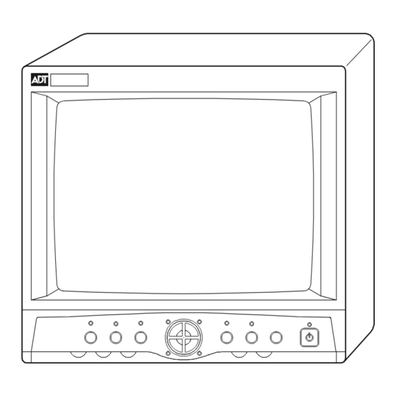
Page 10: Monitor Settings / Controls
Both RJ11 and BNC connections for cameras. On-screen display includes date, time, alarm status, video loss and 8-character camera titles. Nonvolatile program memory saves all user settings and protects all user settings against power loss. MONITOR SETTINGS / CONTROLS FRONT PANEL CONTROLS The following illustration and text describe the buttons, controls, and LED’s on the front of the observation monitor. -
Page 11: Color
Color The Color control adjusts for the color saturation level. Turn clockwise to increase the saturation (high color) and counter clockwise to reduce the saturation (low color). TALK Button / LED Press and hold the TALK button to send audio from the monitor’s built-in microphone to an optional intercom. -
Page 12: Contrast
Contrast Adjust the contrast control to change the overall picture or display contrast. Turn clockwise to increase the contrast; counter clockwise to decrease. VCR Button / LED The VCR button will place the unit into a tape review mode allowing tape playback and zoom of the playback image. -
Page 13: Back Panel Connections
BACK PANEL CONNECTIONS The illustration and following text describe the connections and switches on the back of the observation monitor. ALARM AC IN AC IN Socket The AC IN socket connects the monitor to a suitable wall outlet with the supplied power cord. -
Page 14: Alarm Out Terminal Strip
ALARM OUT Terminal Strip This is a dry relay contact output that changes state whenever an alarm is received on the monitor. The contacts are rated for a maximum of 24V dc at 1 Amp. When the relay output is connected to NO and C, the connection opens upon alarm. When the relay output is connected to NC and C, the connection closes upon alarm. -
Page 15: Installation
INSTALLATION CONNECTING CAMERAS TO THE MONITOR The observation monitor must be installed by qualified service and installation personnel. The installation must be in accordance with all local and national electrical and mechanical codes. Perform the following steps to install the observation monitor. A. - Page 16 BACK OF BNC CAMERA VIDEO OUT BACK OF MODULAR CAMERA C A1 C A2 C A3 C A4 A LARM AC IN BNC Cable BNC Cable connector to Monitor connector to Camera Modular Cable Modular Cable connector to Camera connector to Monitor...
-
Page 17: Connecting A Vcr To The Monitor
CONNECTING A VCR TO THE MONITOR The observation monitor may be installed with a standard VCR, a security event/time- lapse recorder, or a digital recorder. Perform the following steps to install a video recorder. A. Place the recorder in a convenient location near the installed observation monitor. NOTE: Recorder not included with monitor. - Page 18 CONNECTIONS WITH MODULAR-TYPE CABLES BACK VIEW OF MONITOR ALARM AC IN TYPICAL TIME LAPSE RECORDER AUDIO VIDEO RCA To BNC Adaptor AUDIO OUT VCR Interconnection cable AUDIO IN VIDEO IN VIDEO OUT TYPICAL EVENT RECORDER AUDIO VIDEO CH3 CH4 VCR Interconnection cable...
- Page 19 CONNECTIONS WITH BNC-TYPE CABLES BACK VIEW OF MONITOR ALARM AC IN TYPICAL TIME LAPSE RECORDER VIDEO AUDIO VCR Interconnection cable VIDEO IN VIDEO OUT TYPICAL EVENT RECORDER VIDEO AUDIO CH3 CH4 VCR Interconnection cable VIDEO IN VIDEO OUT...
-
Page 20: Connecting Alarming Devices To The Monitor
CONNECTING ALARMING DEVICES TO THE MONITOR The monitor has the capability to annunciate alarms and activate a recorder or other external alarm device when an alarm is received at the observation monitor. Perform the following steps after the installation of the monitor. A. -
Page 21: Connecting A 2-Way Intercom To The Observation System
CONNECTING A 2-WAY INTERCOM TO THE OBSERVATION SYSTEM The monitor has the ability to have a two-way intercom between the monitor and the camera location. Perform the following steps after installing the monitor. A. Install the intercom station in a suitable location. The typical mounting height should be between 30”... -
Page 22: Functional Operation
FUNCTIONAL OPERATION DISPLAY FORMATS Quad Multi-Screen Display When power is first applied to the unit, the monitor displays a quad screen with four camera pictures. If less than four cameras are installed the quadrant for the missing cameras will appear as black. The MODE LED and camera LED’s for the installed cameras will be ON. -
Page 23: Vcr Playback
VCR Playback Pressing the VCR button on the front of the monitor activates the VCR Playback mode. In this mode the signal from the connected VCR is transmitted to the monitor. The image viewed on the screen will show exactly what is being recorded on the VCR. During this operation, the LED above the VCR button turns ON. -
Page 24: Video Loss Alarm
The HOLD TIME determines the duration of the alarm. This can be found on the ALARM menu under the ALARM DURATION submenu. The dwell time of the buzzer and relay will begin when an alarm occurs and stops at the end of the Alarm Hold Time. NOTE: When the unit is in the Setup Mode, the alarm operation is disabled and it will not recognize an alarm event. -
Page 25: On Screen Display (Osd) Menu
camera is heard on the monitor speaker. While in the quad or PIP modes, the audio channel indicator (small square) appears in the window of the selected camera. To select an audio channel, put the unit in quad mode then press the TALK button twice quickly. -
Page 26: Time, Date
Control Description MENU Press once to bring up the MAIN MENU. The MENU LED lights. Press a second time to exit the menu mode. Pressing this button while in a sub-menu returns to the upper menu screen. Moves the cursor down or scrolls through the available options. Moves the cursor up or scrolls through the available options. -
Page 27: Date
Date The DATE setting is used to set the current date. The format displayed on the screen is dependent on the DATE FORMAT options set in the preceding step. Use the following steps to set the current date. Step Action Press until DATE is highlighted. - Page 28 CAMERA TITLES 1. CAMERA 1 : CA 1 2. CAMERA 2 : CA 2 3. CAMERA 3 : CA 3 4. CAMERA 4 : CA 4 5. DISPLAY : ON Camera numbers 1-4 on the CAMERA TITLES setup screen are used to set each camera title.
-
Page 29: Pip Setup
Step Action Press until DISPLAY is selected, then press the SEL button to select the option. Select the desired option (ON or OFF) using the buttons. Press the SEL button. The selected option is saved and the cursor moves back to DISPLAY. PIP Setup The PIP setup screen is used to set the size and position of the PIP screen display. -
Page 30: Alarm
ALARM The ALARM setup screen is used to select the Alarm Input, the Video Loss Alarm, the Alarm Display, and the Alarm Time. ALARM 1. ALARM INPUT 2. VIDEO LOSS ALARM 3. ALARM DISPLAY 4. ALARM TIME Alarm Input The ALARM INPUT setting defines the ALARM INPUT way connectors respond to external input 1. -
Page 31: Video Loss Alarm
Step Action Press to move the cursor to the Alarm LATCH option. Press SEL to select the option. Press to change the value. Select from the following: • ON : All alarm messages and the LED indicators of the alarmed cameras will blink until the alarm hold time expires. - Page 32 Step Action Press to move the cursor to CAMERA 1 of the VIDEO LOSS ALARM options then press the SEL button. Press to change the value. Select from the following: • ON: Executes video loss alarm operation during loss of video. This is the default setting.
-
Page 33: Alarm Display
Alarm Display The ALARM DISPLAY setting is used to ALARM DISPLAY select the display format regardless of the video loss alarm when the external DISPLAY alarm occurs. The display options are QUAD QUAD or FULL format. The default FULL setting is QUAD. Alarm Time The ALARM TIME option allows the user ALARM TIME... -
Page 34: Sequence
SEQUENCE The SEQUENCE setup menu allows the user to select whether or not to display cameras in the sequential switching modes, and if so, to specify the duration of time each camera is displayed. SEQUENCE ORDER DWELL 1: CA 1 03 SEC 2: CA 2 03 SEC... -
Page 35: Picture Adjust
PICTURE ADJUST The PICTURE ADJUST menu allows you to modify the picture quality of the selected quadrant. Adjustments can be made to each cameras brightness, contrast, color, and tint setting. The levels are controlled by 64 steps from MIN to MAX. The 00 setting is the normal value (also the default setting). -
Page 36: New Code
PASSWORD INCORRECT PASSWORD ENTER PASSWORD _ _ _ _ ACCESS DENIED ENTER THE 4 DIGIT CODE USING CAMERA KEYS (1-4) New Code To change the password, use the ENTER NEW CODE / RE-ENTER NEW CODE configuration option. Use the following steps to change the password. Step Action On the CONFIGURATION screen, press... -
Page 37: Key Lock
WARNING THIS WILL CHANGE FACTORY DEFAULT ALL USER SETTINGS TO IS DONE THE FACTORY DEFAULT. Use the following steps to reset the unit to the factory defaults. Step Action Press until FACTORY DEFAULTS is selected, then press SEL. A warning message is displayed in the message portion of the screen. Select the desired option (YES or NO) using the buttons, then press the SEL button. -
Page 38: Audio Mark
ALARM HISTORY PAGE1 21:05:36 02/28/2002 20:05:36 02/28/2002 19:05:36 02/28/2002 18:05:36 02/28/2002 17:05:36 02/28/2002 16:05:36 02/28/2002 15:05:36 02/28/2002 14:05:36 02/28/2002 13:05:36 02/28/2002 12:05:36 02/28/2002 PRESS SELECT TO CLEAR Step Action Press on the Configuration screen until ALARM HISTORY is selected. Press SEL to display the current alarm history for all cameras as of the last reset date. -
Page 39: Vis Trigger Pulse
VIS Trigger Pulse The VIS TRIGGER PULSE (Vertical Interval Switching) option allows the user to select the rolling-free sequencing picture or the VCR output picture. Use the following steps to set the VIS TRIGGER PULSE. Step Action Press on Configuration screen until VIS TRIGGER PULSE is selected. - Page 40 {This page intentionally left blank.}...
-
Page 41: Specifications
SPECIFICATIONS Format Quad Screen Display Operating defaults Display Live Time/date display Factory defaults Date US (MM/DD/YYYY) Camera titles ON (CA1 – CA4) PIP size PIP location Alarm input polarity Normally Open (NO) Alarm display QUAD Alarm buzzer Alarm hold time 20 seconds Alarm latch Alarm relay... - Page 42 Gray shades 256 (8 bits) Display Color 16 million Full-screen format 720 x 480 pixels Quad screen 360 x 240 pixels PIP inset 240 x 160 pixels, 180 x120 pixels Zoom display Interpolated, 720 x480 pixels Display rate Real time refresh rate (60 fields per sec per quadrant) Resolution 400 TV lines (at center) MENU...
- Page 43 {This page intentionally left blank.}...
- Page 44 A-O14QCP2 Doc # xxxx...
Need help?
Do you have a question about the A-O14QCP2 and is the answer not in the manual?
Questions and answers