Turbo Air TPR-67SD Service Manual
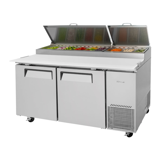
Pizza prep table
Hide thumbs
Also See for TPR-67SD:
- Service manual (24 pages) ,
- Installation and operation manual (9 pages)

Related Manuals for Turbo Air TPR-67SD


Summary of Contents for Turbo Air TPR-67SD
- Page 1 1250 Victoria street CARSON, CA 90746 TEL: 310-900-1000 FAX: 310-900-1077 Toll Free: 1-800-627-0032 U.S.A. & Canada http://www.turboairinc.com...
- Page 2 Commercial Refrigerator Service Manual Pizza Prep Table Model No.: TPR-67SD TPR-93SD...
- Page 4 Commercial Refrigerator Service Manual Pizza Prep Table Model No.: TPR-67SD TPR-93SD...
-
Page 5: Table Of Contents
TABLE OF CONTENTS 1. FEATURE CHART 1-1. FRONT VIEW 1-2. PLAN VIEW AND SIDE VIEW 2. WIRING DIAGRAM 2-1. TPR-67SD 2-2. TPR-93SD 3. PART DETAILS 3-1. DUCT PANEL (EXTERIOR) 3-2. EVAPORATOR FAN MOTOR GUARD 3-3. EVAPORATOR FAN MOTOR ASSEMBLY 3-4. EVAPORATOR COIL 3-5. -
Page 6: Feature Chart
1. FEATURE CHART 1-1. FRONT VIEW... -
Page 7: Plan View And Side View
FEATURE CHART 1-2. PLAN VIEW AND SIDE VIEW... -
Page 8: Wiring Diagram
2. WIRING DIAGRAM 2-1. TPR-67SD 2-2. TPR-93SD... -
Page 9: Part Details
3. PART DETAILS 3-1. AIR DUCT PANEL (EXTERIOR) PAN DUCT AIR DUCT PANEL (LOUVERED PANEL) 3-2. EVAPORATOR FAN MOTOR GUARD EVAPORATOR FAN MOTOR GUARD POWER SWITCH THERMOSTAT KNOB THERMOSTAT PANEL EVAPORATOR FRONT DUCT PANEL The position of the POWER SWITCH and the THERMOSTAT KNOB can be changed for improvement without notice. -
Page 10: Evaporator Coil
PART DETAILS 3-4. EVAPORATOR COIL INLET OUTLET ACCUMULATOR 3-5. AIR GUIDE PANEL & PAD AIR GUIDE PANEL (B) AIR GUIDE PANEL (C) AIR GUIDE PANEL (A) AIR GUIDE PAD (E-PS) 3-6. DUCT PANEL (INTERIOR) PAN DUCT AIR DUCT PANEL (LOUVERED PANEL) AIR FLOW... -
Page 11: Cabinet
PART DETAILS 3-7. CABINET FRONT COVER CABINET FRONT COVER CONDENSER COIL 3-8. THERMOSTAT & POWER SWITCH THERMOSTAT POWER SWITCH 3-9. CONDENSER COIL INLET OUTLET BRACKET... -
Page 12: Condenser Fan Motor Assembly
PART DETAILS 3-10. CONDENSER FAN MOTOR CONDENSER FAN MOTOR CONDENSER FAN BLADE BRACKET 3-11. COMPRESSOR COMPARTMENT PART (FRONT) CONNECTING PIPE (A) CONNECTING PIPE (B) COMPRESSOR CONDENSER COIL CONDENSER FAN MOTOR 3-12. COMPRESSOR COMPARTMENT PART (BACK) SUCTION LINE (B) SUCTION LINE FIXTURE... -
Page 13: Main Components
4. MAIN COMPONENTS 4-1. COMPRESSOR HORSE TYPE OF MODEL PART NAME PART NO. CAPACITY INPUT MAKER POWER MOTOR TPR-67SD 7,638.4BTU/h T6217Z 3020014570 5/8HP CSIR – EMBRACO TPR-93SD (1,925kcal/h) 4-2. COMPRESSOR RELAY, OVERLOAD MODEL RELAY PART NO. OVERLOAD PART NO. MAKER... -
Page 14: Temperature Control Instruction
1. The temperature can be changed by turning the dial knob. Temperature Compressor 2. Compressor is automatically turned on and off by thermostat. Control Cond. Fan Motor (GNA-241L) Cut in and out temperature chart. ˚F Model: TPR-67SD TPR-93SD Cut in 40.1 ± 2.7 Cut Out 21.2 17.1 10.4... - Page 15 6. PARTS-LIST OF PIZZA PREP TABLE Model Part name Code Description TPR-67SD TPR-93SD Caster CASTER 30265L0401 TP5040-22-HDP CASTER BRAKE 30265L0301 TP5040-22-HDP-TLE Door DOOR ASSEMBLY(LEFT) 30200P1710 STAINLESS STEEL +URT DOOR ASSEMBLY(RIGHT) 30200P1700 STAINLESS STEEL +URT DOOR GASKET 30223P0100 PVC-S DOOR BUSHING...
- Page 16 Model Part name Code Description TPR-67SD TPR-93SD EVAPORATOR COIL 30270P0102 Cu EVAPORATOR DRAIN PAN 30211P0202 AL EVAPORATOR FAN MOTOR 3963220410 IS-4420DWSG-1 EVAPORATOR FAN BLADE 30218B0300 AL, ø200 EVAPORATOR FAN MOTOR GUARD 30214P2500 HIPS, ø200 EVAPORATOR FRONT DUCT PANEL 30269P0110 STAINLESS STEEL...
-
Page 17: Replacement Of Main Components
7. REPLACEMENT OF MAIN COMPONENTS * Surely turn the unit off before replacing any part of it! 7-1. REPLACING THE DOOR A. Unscrew the door hinge top. B. Lift the door. Replace the old one with new. Insert the door hinge top into the door bush. Angle between the door line and the hinge bracket line is 90˚... -
Page 18: Replacing The Mullion
REPLACEMENT OF MAIN COMPONENTS 7-2. REPLACING THE MULLION A. Remove all shelves from inside of the unit and unscrew the screws on each side of the mullion. B. Rip off the mullion cover carefully. C. Disconnect the mullion heater and pull out the mullion insulator. D. -
Page 19: Replacing The Cabinet Frame Heater
REPLACEMENT OF MAIN COMPONENTS 7-3. REPLACING THE CABINET FRAME HEATER A. Insert '-' screw driver into the gap between the cabinet frame and the cabinet frame cover. B. Separate the end of the cabinet frame cover and pull it out continuously to the end of the other side. -
Page 20: Replacing The Evaporator Fan Motor
REPLACEMENT OF MAIN COMPONENTS 7-4. REPLACING THE EVAPORATOR FAN MOTOR A. Unscrew the screws on the evaporator front duct panel. B. Take it apart and disconnect the thermostat and the power switch from the main harness. C. Unscrew the screws on the evaporator fan motor bracket using a short '+' screw driver. D. -
Page 21: Evaporator Leak Checking
REPLACEMENT OF MAIN COMPONENTS 7-5. EVAPORATOR LEAK CHECKING A. Unscrew a hidden screw at the position as the picture below. B. Lift up the front grille panel and pull it out. Cut the silicon off around the cabinet front cover using a knife and pull it out. C. -
Page 22: Replacing The Compressor Compartment Part
REPLACEMENT OF MAIN COMPONENTS 7-6. REPLACING THE COMPRESSOR COMPARTMENT PART A. Unscrew the screws on the compressor base. B. Disconnect the suction line connection by melting it using a torch. C. Check the harness ties and the ground screws. Untie them and unscrew them for safety. -
Page 23: Replacing The Evaporator
REPLACEMENT OF MAIN COMPONENTS 7-7. REPLACING THE EVAPORATOR A. Unscrew the screws on the brackets at the each rear corner of the unit as pictures below. B. Remove all the shelves from inside of the unit. Unscrew the screw on the brackets at the front top position inside of the unit as pictures below. - Page 24 REPLACEMENT OF MAIN COMPONENTS C. Unscrew all the screws on the air duct panel and pull it out carefully. Unscrew all the screws on the pan duct. You can see the black lines around the corner inside top of the unit. Cut the black silicon bonding lines of the counter top.
- Page 25 REPLACEMENT OF MAIN COMPONENTS D. Lift up the pan duct and put it out as the picture below. E. There is a insulator that guides cold air flow into the air duct panel. Pull it out. You can see the duct panel which shape is ' '. F.
- Page 26 REPLACEMENT OF MAIN COMPONENTS H. Unscrew the screws on the duct panels in front of the evaporator. I. Unscrew the screws on the evaporator fan motor bracket and take it apart from the unit. Disassemble the connecting pipe between the evaporator coil and the suction line by melting connections using a torch.
- Page 27 ABOUT THIS MANUAL ABOUT THIS MANUAL...
Need help?
Do you have a question about the TPR-67SD and is the answer not in the manual?
Questions and answers