
Related Manuals for Kenwood SVT-M700

Summary of Contents for Kenwood SVT-M700
-
Page 1: Service Manual
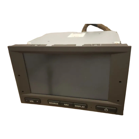
6.5 INCHES TV MONITOR SVT-M700 SERVICE MANUAL © 2002-9 PRINTED IN JAPAN B51-7977-00 ( N ) 1864 SAAB GENUINE Destination Europe GENUINE NUMBER 55 21 372... -
Page 2: Block Diagram
SVT-M700 BLOCK DIAGRAM TOUCH PANEL SWITCH ASSY V IN (X35- ) (A/2) (X14- ) from X14 X-DT Y-DT LCD ASSY IC202 to STC-700 MI-COM IC701 IC301,Q302,303 COMP VIDEO COMP VIDEO NAVI SYNC VCOM DRIVER to X35 C. TRAP V COM... - Page 3 SVT-M700 COMPONENTS DESCRIPTION Ref.No. Component Name Application/Function Operation/Condition/Compatibility 2SA1428 Voltage limiter Power supply voltage limiter and Ripple filter 2SC2412K Q201 2SC4081 Q202 2SA1576A Video buffer Video signal amplifier and buffer Q203 2SC4081 When the panel reset SW is pressed, Q301 is turned on, and the system MI-...
- Page 4 SVT-M700 MICROCOMPUTER’S TERMINAL DESCRIPTION IC301 (VIDEO CONTROL UNIT : X14-9172-70) Pin No. Pin Name Description Processing Operation M DATAC Data output to STC-700 M CLK Data clock input from STC-700 OSD CS OSD chip select output OSD DO OSD data output...
-
Page 5: Microcomputer's Terminal Description
SVT-M700 MICROCOMPUTER’S TERMINAL DESCRIPTION Pin No. Pin Name Description Processing Operation RED/GREEN LED colour switching output Not used (N.C.) BVDD Bus interface positive power supply connection terminal Connected to BU5V lines. BVSS Bus interface ground connection terminal Connected to GND lines. -
Page 6: Test Mode
SVT-M700 TEST MODE • Preparation 1. Prepare the H/U (STC-700), and connect the power cord and the interface cord to it. 2. Prepare the remote controller (RC-DV100), and the op- eration mode selector switch is made the television mode. 1. Test mode 2. - Page 7 SVT-M700 ADJUSTMENT • Preparation 1. Prepare the H/U (STC-700) and the NAVI unit (KNA-DV2200/S), and connect the power cord and the interface cord to it. 2. Prepare the remote controller (RC-DV100), and the operation mode selector switch is made the television mode.
- Page 8 SVT-M700 ADJUSTMENT Item Adjustment method/Adjustment value Conditions 2. Screen display start 1. Display the OSD (RADIO SETTINGS) screen. • Input signal : OSD position adjustment 2. Adjust that the 3 vertical lines of A and B part is to be inside the...
- Page 9 SVT-M700 ADJUSTMENT Item Adjustment method/Adjustment value Conditions 3-5. Black limiter 1. Select CH : 5 by using the remote controller. • Input : Video in adjustment 2. Observe the waveform of TP25 on an oscilloscope. • Input signal : Composite CH : 5 3.
- Page 10 SVT-M700 ADJUSTMENT Item Adjustment method/Adjustment value Conditions 3-9. Gamma 2 adjustment 1. Select CH : 12 by using the remote controller. • Input : Video in CH : 12 2. Observe the waveform of TP25 on an oscilloscope. • Input signal : Composite 3.
- Page 11 SVT-M700 ADJUSTMENT Item Adjustment method/Adjustment value Conditions 3-13. B Sub-contrast 1. Select CH : 15 by using the remote controller. • Input : Video in adjustment 2. Observe the waveform of TP26 on an oscilloscope. • Input signal : Composite CH : 15 3.