Table of Contents
Advertisement
Quick Links
Download this manual
See also:
Installation Manual
Advertisement
Table of Contents

Related Manuals for Uplogix 500

Summary of Contents for Uplogix 500
- Page 1 Startup Guide for Local Managers Version 5.1 January 2015 www.uplogix.com...
- Page 2 Information in this document is subject to change without notice. © 2015 Uplogix, Inc. All Rights Reserved. Uplogix, the Uplogix logo, and SurgicalRollback are trademarks of Uplogix, Inc. in the United States and other jurisdictions. All other marks referenced are those of their respective owners.
-
Page 3: Table Of Contents
Initial configuration via console connection ................14 Configuring the Local Manager for your LAN ................15 Configuring an optional Pulse server ..................15 Configure communication with the Uplogix Control Center ............16 Configuring Power Control and Managed Device Ports .............. 16 Out of Band ......................18 Initial Connections ...................... -
Page 4: About This Guide
About this guide This guide describes the procedures for getting the Local Manager up and running in your environment. More detailed instructions can be located in other guides located on the Uplogix Support portal. Information in this document is subject to change without notice. Please visit support.uplogix.com... -
Page 5: Package Contents
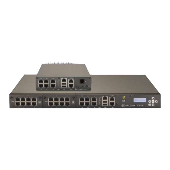
Package Contents Unpacking the shipping box Verify that you have received the following items: Uplogix 500 Local Manager Uplogix 5000 Local Manager 1 power supply and cord 2 US power cords (AC unit) or 2 Molex to 3-wire power cords (DC unit) ... -
Page 6: Hardware Installation & Connections
Hardware Installation & Connections Installing the Uplogix 500 Uplogix 500 Making the connections required for initial configuration To complete initial setup, you must connect the Local Manager to a power source. Connecting power The Local Manager uses an external power supply, which is shipped with the device. -
Page 7: Connecting A Workstation
Caution: Use only the power supply shipped with the Local Manager 500. Using a different power supply will void your warranty and may damage the equipment. Connect the power supply to the DC connector on the back of the device. -
Page 8: Installing The Uplogix 5000 Local Manager
If your management network is fiber based, connect to the SFP in the option slot. If GE-0 or GE-1 are connected to the network, they will take precedence over the fiber connection. Installing the Uplogix 5000 Local Manager Uplogix 5000... -
Page 9: Making The Connections Required For Initial Configuration
At the end of the boot sequence, it displays the message Uplogix status good. DC Model Available on the Uplogix 5000 only. The DC Local Manager uses a power cord with a Molex connector (part number: 39-01-4041) end and a three-wire split out. -
Page 10: Making The Remaining Connections
Power on the unit by pressing the middle keypad button. The display on the front panel will illuminate and display progress messages as the device boots. At the end of the boot sequence, it displays the message Uplogix status good. Description... - Page 11 If your workstation has a DB-9 serial port, use the DB-9 to RJ-45 adaptor provided by Uplogix (see diagram below) and a straight-through Ethernet cable to connect to the console port. If your workstation does not have a DB-9 serial port, you will need to use a USB to DB-9 serial adaptor together with a straight-through Ethernet cable and the DB-9 adaptor provided by Uplogix to connect to the console port.
-
Page 12: Quick Setup
You may configure the Local Manager as a standalone network management tool or configure it to be managed by the Uplogix Control Center. The Uplogix 500 and 5000 Local Managers can be initially provisioned via their console connections. The Uplogix 5000 Local Manager can alternatively be provisioned via the front panel keypad. - Page 13 For each setting, you can accept the default or existing setting by pressing the enter key. 1. Press the enter key on the keypad to access the menu. The > character appears to the left of the currently selected option. Press enter or the right arrow button to access the configuration screens.
-
Page 14: Initial Configuration Via Console Connection
Pulse Server IP: 127.000.000.001 8. Enter an IP address for the Uplogix Control Center only if this unit is to be managed by an Uplogix Control Center. Otherwise, do not enter an IP address at this prompt. Press enter to skip to the next configuration item. -
Page 15: Configuring The Local Manager For Your Lan
Configuring the Local Manager for your LAN The Local Manager is initially configured to use DHCP. You can use the show system ip command to display current management Ethernet network settings. To configure the Local Manager’s network addressing, use the config system ip command. The Local Manager displays the current settings, and presents a prompt asking whether you want to make changes. -
Page 16: Configure Communication With The Uplogix Control Center
Use the config system management command if you wish to manage the Local Manager with a Control Center. Uplogix recommends using the default values and setting the ‘Hostname or IP:’ field to contain the hostname or IP address of your Control Center. - Page 17 For full documentation of configuring managed devices and power controllers, see the Configuring Managed Devices and Power Control section of the Local Manager User Guide, available on the Uplogix support website, support.uplogix.com. Managed Device Ports The device ports for the Local Manager are initially configured as native. When a supported device is connected, the port must be initialized for the specific device in order to enable advanced management functionality.
-
Page 18: Out Of Band
Out of Band There are a variety of out of band options used by for the Local Manager. This section will cover the initial connections required for each type. In most cases the modem option card will be pre-installed in the Local Manager option slot. If it is not, refer to the Local Manager Install Guide for installation instructions. - Page 19 Analog modem Most external analog modems can be connected to the Local Manager DB9 modem card. This connection is made with a DB9 to DB9 cable, generally provided with your external modem. Exactly like the embedded analog modem, the external analog modem will need a connection (over RJ11 cable) to an analog service provider.
-
Page 20: Reference
– Logs your user account out of the CLI. config system ip – Starts the Local Manager network configuration wizard. config system management – Allows you to configure the Local Manager to use an Uplogix Control Center (UCC) for system management. -
Page 21: Port Resource Commands
~ commands – When in an active terminal session in to a managed device you can issue commands prefaced by the tilde (~) character to access Uplogix Local Manager functions. ~ <ENTER> will terminate the session and return you to the Local Manager CLI. - Page 22 config outlet – Begins the outlet mapping wizard, allowing you to associate power controller outlets with Local Manager ports. power <port #/#> on/off/cycle – Manually applies or cycles power to a specified port. Startup Guide for Local Managers...
-
Page 23: Support And Regulatory Information
Support and regulatory information Getting technical support The Uplogix technical support web site allows you to open and review support requests, browse the knowledge base and download software updates. You must have a user account to view this site. Requesting an account To create an account, send an email to support@uplogix.com...
Need help?
Do you have a question about the 500 and is the answer not in the manual?
Questions and answers