Table of Contents
Advertisement
Advertisement
Table of Contents
Troubleshooting

Related Manuals for Fore Systems ES-2810

Summary of Contents for Fore Systems ES-2810
- Page 1 FORE Systems óæ ES-2810 Ethernet Switch User’s Manual MANU0330-02 - Rev. A - November, 1998 Firmware Version 2.31 Stack View Version 2.00 FORE Systems, Inc. 1000 FORE Drive Warrendale, PA 15086-7502 Phone: 724-742-4444 FAX: 724-772-6500 URL: http://www.fore.com...
-
Page 2: Legal Notices
NOTE: The ES-2810 Ethernet Switch has been tested and found to comply with the limits for a Class A digital device, pur- suant to Part 15 of the FCC Rules. These limits are designed to provide reasonable protection against harmful interference when the equipment is operated in a commercial environment. - Page 3 ETL certified to meet Information Technology Equipment safety standards UL 1950, CSA 22.2 No. 950, and EN 60950. TRADEMARKS FORE Systems, ForeRunner, and ForeView are registered trademarks of FORE Systems, Inc. ForeRunnerLE and CellPath are unregistered trademarks of FORE Systems, Inc. All other brands or product names are trademarks or registered trademarks of their respective holders.
-
Page 5: Table Of Contents
Static-free Working Area ........1-12 FORE Systems ES-2810 Ethernet Swtich User’s Manual... - Page 6 Navigating through FORE Stack View......2-6 FORE Systems ES-2810 Ethernet Swtich User’s Manual TOC - 2...
- Page 7 Diagnostic Details Window ........2-29 FORE Systems ES-2810 Ethernet Swtich User’s Manual...
- Page 8 Local Management ..........3-15 FORE Systems ES-2810 Ethernet Swtich User’s Manual...
- Page 9 Changing the Cost of the Path ....... . 3-34 3.19.4 Changing Priority of the Port in the Spanning Tree ....3-34 FORE Systems ES-2810 Ethernet Swtich User’s Manual TOC - 5...
- Page 10 RMON Events ..........5-11 FORE Systems ES-2810 Ethernet Swtich User’s Manual...
- Page 11 The Recovery Manager ..........5-36 FORE Systems ES-2810 Ethernet Swtich User’s Manual...
- Page 12 Restoring Software ......... 7-3 FORE Systems ES-2810 Ethernet Swtich User’s Manual...
- Page 13 Files Suitable for TFTP Transfer ....... 7-16 7.9.3 Transferring Files to and From the Switch using TFTP....7-17 FORE Systems ES-2810 Ethernet Swtich User’s Manual TOC - 9...
- Page 14 IP Addresses ..........A-16 FORE Systems ES-2810 Ethernet Swtich User’s Manual...
- Page 15 IP Learning ........A-30 FORE Systems ES-2810 Ethernet Swtich User’s Manual...
- Page 16 Table of Contents FORE Systems ES-2810 Ethernet Swtich User’s Manual TOC - 12...
-
Page 17: List Of Figures
Figure 1.2 Rear Panel of the ES-2810 ....... 1-6 Figure 1.3 Attaching the Mounting Brackets . - Page 18 Synchronization Manager Dialog Box ..... 5-40 Figure 5.26 Switch Position Organizer Dialog Box ..... 5-41 FORE Systems ES-2810 Ethernet Swtich User’s Manual LOF - 14...
- Page 19 Spanning Tree and VLANs ......A-29 FORE Systems ES-2810 Ethernet Swtich User’s Manual...
- Page 20 List of Figures FORE Systems ES-2810 Ethernet Swtich User’s Manual LOF - 16...
- Page 21 Technical Assistance Center (TAC) using the information on page ii. Chapter Summaries Chapter 1 - Introduction to the ES-2810 - Provides an overview of the ES-2810 switch and installation procedures for the switch and its modules. Chapter 2 - FORE Stack View - Provides an overview of the Stack View network manage- ment software for the ES-2810.
-
Page 22: Technical Support
Preface Technical Support In the U.S.A., you can contact FORE Systems’ Technical Assistance Center (TAC) using any one of the following methods: You can receive on-line support via TACtics On-line at: http://www.fore.com/tac You can contact Technical Support via e-mail at: support@fore.com... - Page 23 As in the following example, any messages appearing on your screen during software installa- tion and network interface administration will appear in Courier font to distinguish them from the rest of the text. Are all four conditions true? ..FORE Systems ES-2810 Ethernet Switch User’s Manual...
- Page 24 Important Information Indicators To call your attention to important information that must be reviewed to ensure correct and complete installation, as well as to avoid problems with your software, FORE Systems utilizes the following CAUTION/NOTE indicators. Information contained in CAUTION statements is important for proper installation/opera- tion.
- Page 25 This chapter covers the topics described in Table 1.1. Table 1.1 - Topics Discussed in this Chapter Topic See Page Introduction to the product page 1-2 Front Panel page 1-4 Rear Panel page 1-6 Installation page 1-7 1 - 1 FORE Systems ES-2810 Ethernet Switch User's Manual...
-
Page 26: Introduction To The Es-2810
1.1 Introduction to the product 1.1.1 Purpose of the Switch The ES-2810 uses your existing network cables to integrate switching technology into your computer network. Each device in a workgroup or a network segment can communicate at a full wire-speed of 10Mbps or 100Mbps to provide: •... -
Page 27: Software Features
• BOOTP and TFTP support • Control over user access rights • Creation of virtual LANs • Stand-alone (per switch or stack) or distributed (switch network) VLAN • IGMP Pruning 1 - 3 FORE Systems ES-2810 Ethernet Switch User’s Manual... -
Page 28: Front Panel
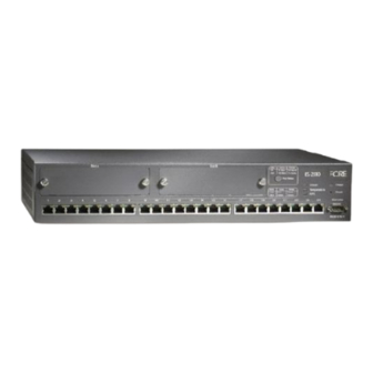
1.2.2 View of the Front Panel The front panel of the switch is shown below: 1589 Figure 1.1 - The Front Panel of the ES-2810 1.2.3 Front Panel Ports These ports are on the front panel: Table 1.2 - Front Panel Ports... -
Page 29: Slots For Media Modules
The buttons on the front panel have the following functions: Table 1.4 - Front Panel Buttons Button name Function Port Status Shows the operational status of each port. Reset Reset or enter Maintenance Mode or Recovery Mode 1 - 5 FORE Systems ES-2810 Ethernet Switch User’s Manual... -
Page 30: Rear Panel
The rear panel of the switch is shown below: Input 100-120VAC/2A 200-240VAC/1A 47Hz-63Hz Redundant Power Supply (RPS) 1741 Figure 1.2 - Rear Panel of the ES-2810 1.3.3 Rear Panel Parts The switch’s rear panel has the following parts: Table 1.5 - Rear Panel Components Part Function Fan outlet Cools the internal circuitry of the switch. -
Page 31: Installation
One ES-2810 One power cord (suitable for your power outlet) One mounting kit One CD-ROM One Console cable One Quick Start FORE Documentation CD (including this on-line manual) FORE Release Notes 1 - 7 FORE Systems ES-2810 Ethernet Switch User’s Manual... -
Page 32: Check The Package Contents
Warnings and the instructions earlier in this guide. • The Release Notes included with the switch. • The README.TXT file on the CD-ROM. This gives a general description of the software and specific requirements. 1 - 8 FORE Systems ES-2810 Ethernet Switch User’s Manual... -
Page 33: Positioning And Installing The Switch
Ensure that the air intake (on the left) and fan outlets (on the right side and rear) are not blocked. The switch’s lifetime and operational reliability WARNING! can be seriously degraded by inadequate cooling. 1 - 9 FORE Systems ES-2810 Ethernet Switch User’s Manual... -
Page 34: Rack Requirements
Standard 19-inch rack with side support rails. • 3 mm screwdriver. • Customer-supplied screws for securing the switch in the rack. Mounting screws are not provided because the required sizes may vary from rack to rack. 1 - 10 FORE Systems ES-2810 Ethernet Switch User’s Manual... -
Page 35: In An Equipment Rack
Make sure that the temperature of the rack environment does not exceed the recommended operating temperature for the switch. 1 - 11 FORE Systems ES-2810 Ethernet Switch User’s Manual... -
Page 36: Installing A Module
Connect yourself to a non-painted/non-isolated part of the grounded switch (for example the back panel) using a wrist strap with 1MΩ resistance to ensure that you carry the same electrostatic charge as the enclosure. Remove the plate covering the slot. 1 - 12 FORE Systems ES-2810 Ethernet Switch User’s Manual... -
Page 37: Installing A Module
Pull the module gently to disengage the connectors fully from the socket on the motherboard. Slide the module out completely. Cover the empty module port with the plate and secure using the screws. 1 - 13 FORE Systems ES-2810 Ethernet Switch User’s Manual... -
Page 38: Connecting Other Devices
Straight-through cable 1:1 1.7.4 RJ-45 Connector Pin Assignments The RJ-45 ports on the front of the switch have the following pin assignments: Table 1.8 - RJ-45 Connector Pinouts Pin number Function 1 - 14 FORE Systems ES-2810 Ethernet Switch User’s Manual... -
Page 39: Connecting A Device To The Rj-45 Ports
Connect the other end to the 100Base-TX connection on the device. 1.7.6 Cable for the Console Port If you connect a PC (via the Console Port), then use a null-modem cable. 1 - 15 FORE Systems ES-2810 Ethernet Switch User’s Manual... -
Page 40: Connecting The Power
Make sure that the blue wire is connected to the terminal marked with the letter N or colored black. Make sure that the brown wire is connected to the terminal marked with the letter L or colored red. 1 - 16 FORE Systems ES-2810 Ethernet Switch User’s Manual... -
Page 41: Power Supply To A Rack
To avoid overloading the circuit and damaging the wiring of the power supply, the power supply to the rack must be adequate to cover the extra power consumed by the switch. 1 - 17 FORE Systems ES-2810 Ethernet Switch User’s Manual... -
Page 42: Power Up
If the Status LED remains red, then the switch has not started successfully. Try to restart it; if the switch does not start, contact your dealer. Look at the other front panel LEDs during start-up and check that they are operating correctly. 1 - 18 FORE Systems ES-2810 Ethernet Switch User’s Manual... -
Page 43: Port Led States
Collision detected (with half duplex). randomly Port enabled, link pulse active. Orange, solid Port disabled by management. Green and Orange both solid Port disabled by a hardware fault, or no hardware con- nected. 1 - 19 FORE Systems ES-2810 Ethernet Switch User’s Manual... -
Page 44: Default Settings After Start-Up
Although the switch continues to operate without problems, we recommend that you change certain parameters to suit your own requirements. Follow the instructions in Chapter 2 to change the configuration while the switch is operating. 1 - 20 FORE Systems ES-2810 Ethernet Switch User’s Manual... -
Page 45: Other Leds On The Front Panel
Temperature is too high and the switch will shut down. Green Off: No RPS connected. Solid: RPS connected, but not needed. Orange Normal power supply has failed and the RPS has taken over. 1 - 21 FORE Systems ES-2810 Ethernet Switch User’s Manual... -
Page 46: Port Status Button
LEDs changes for a period of 5 seconds, where they have the following meaning: Table 1.13 - Port LED Indicator Colors and Meanings Color Meaning Left (Speed) Green Off: 10Mbps Solid: 100Mbps Right (Duplex) Orange Off: Half duplex Solid: Full duplex 1 - 22 FORE Systems ES-2810 Ethernet Switch User’s Manual... -
Page 47: Fore Stack View
Using FORE Stack View page 2-5 Device View (Main Display) page 2-20 Explorer page 2-27 Diagnostics Window page 2-28 Trap Window page 2-30 System Window page 2-31 Errors Window page 2-32 2 - 1 FORE Systems ES-2810 Ethernet Switch User’s Manual... -
Page 48: System Requirements
Ensure the IP address for the PC is not changed by the DHCP server. • PCs that use a network management system that uses BootP, DHCP or SNMP Trap Receiving, may have their network management system disabled by FORE Stack View. 2 - 2 FORE Systems ES-2810 Ethernet Switch User’s Manual... -
Page 49: Installation And Removal
To Install FORE Stack View for Windows Click Install Windows and follow the on-screen instructions. When the installation is com- plete, FORE Stack View will start automatically when “Launch FORE Stack View” is selected. 2 - 3 FORE Systems ES-2810 Ethernet Switch User’s Manual... -
Page 50: Removal Of Fore Stack View
2.4 Removal of FORE Stack View 2.4.1 Removal under Windows To remove FORE Stack View under Windows: Close all FORE Stack View programs. Use standard Windows procedures to uninstall FORE Stack View. 2 - 4 FORE Systems ES-2810 Ethernet Switch User’s Manual... -
Page 51: Using Fore Stack View
FORE Stack View uses SNMP to configure all the parameters on your switch, or group of switches (known from here on as a stack), and monitors their activities. Figure 2.2 - FORE Stack View 2 - 5 FORE Systems ES-2810 Ethernet Switch User’s Manual... -
Page 52: Navigating Through Fore Stack View
Information section — provides details about diagnostics, traps, errors and the system. Using this window, you can show activity statistics for the switch (or the stack) and for individual ports. 2 - 6 FORE Systems ES-2810 Ethernet Switch User’s Manual... -
Page 53: Before A Switch Is Contacted
Toolbar and Status Bar can be switched on and off. 2.6.5 Monitoring Menu The Monitoring menu gives access to set the Default Preferences for FORE Stack View. See “Setting the Preferences” on page 2-10. 2 - 7 FORE Systems ES-2810 Ethernet Switch User’s Manual... -
Page 54: Tools Menu
The Help menu has the following commands for the switch: • Help for FORE Stack View. Can also be accessed by selecting the Help icon then clicking on the feature of interest • Help for switch specific topics. 2 - 8 FORE Systems ES-2810 Ethernet Switch User’s Manual... -
Page 55: After A Switch Or Stack Is Contacted
Matrix Module. This simplifies the task of tracing cables, as the ports on the Stack Interface Modules become the same color as the corresponding Matrix Module port. • A color coding chart for FORE Stack View to show the states of switch’s LEDs 2 - 9 FORE Systems ES-2810 Ethernet Switch User’s Manual... -
Page 56: Setting The Preferences
Figure 2.3 - Polling Tab of Preferences Dialog Box Click Polling or Monitor. If you want the polling to happen more frequently than just on opening, click Periodically. Move the Interval slider to the required time. Click OK. 2 - 10 FORE Systems ES-2810 Ethernet Switch User’s Manual... -
Page 57: Setting The Timeout Parameters For Snmp
To change the timeout parameters: Select Monitoring>Preferences. Click Timeouts. Figure 2.4 - Timeouts Tab of the Preferences Dialog Box Change the values. Click OK. 2 - 11 FORE Systems ES-2810 Ethernet Switch User’s Manual... -
Page 58: Setting The Community For Snmp Polling
The community for SNMP polling determines access rights. To change the community: Select Monitoring>Preferences. Click Community. Figure 2.5 - Community Tab of the Preferences Dialog Box Type the new community name. Click OK. 2 - 12 FORE Systems ES-2810 Ethernet Switch User’s Manual... -
Page 59: Installing And Managing Switches
You must assign an IP address (and subnet mask) to the switch on your Local Area Network (LAN). FORE Stack View uses this address for configuration and management purposes. Figure 2.6 - The Install Wizard 2 - 13 FORE Systems ES-2810 Ethernet Switch User’s Manual... -
Page 60: Matrix Module Connected To A New Switch
If you want to manage it as part of a stack, you have the opportunity to assign consecutive IP addresses in the next dialog. Figure 2.7 - Install Wizard New Switch Message 2 - 14 FORE Systems ES-2810 Ethernet Switch User’s Manual... -
Page 61: Managing An Existing Switch Or Stack
Select Device>Manage. The Manage dialog box appears. Type in the switch’s IP Address or MAC address. Select the box if you want to open the switch in a new FORE Stack View window. Click OK. 2 - 15 FORE Systems ES-2810 Ethernet Switch User’s Manual... -
Page 62: Establishing And Expanding A Stack
Configure IP address box is checked. Select Stack Management. Select OK. The Upgrade Wizard starts automatically if software needs to be upgraded. 2 - 16 FORE Systems ES-2810 Ethernet Switch User’s Manual... -
Page 63: Device Tree
The Device Tree displays the separate subnets on your LAN as branches in a tree. This includes a branch that shows all the unconfigured devices on the LAN. Figure 2.10 - The Device Tree 2 - 17 FORE Systems ES-2810 Ethernet Switch User’s Manual... -
Page 64: Identifying Devices
2.10.3 Installing and Managing Switches Double clicking the switch’s IP address or MAC address opens existing switches in the FORE Stack View window, or starts the Install Wizard for new switches. 2 - 18 FORE Systems ES-2810 Ethernet Switch User’s Manual... -
Page 65: Right Mouse Button Commands
Statistics Provides subnet management statistics. History Lists monitored traffic on a subnet. Alarms Enables activity alarms to be set. Logs Sets events defined by Log, Trap or Log and Trap. 2 - 19 FORE Systems ES-2810 Ethernet Switch User’s Manual... -
Page 66: Device View (Main Display)
For example, the LEDs change color according to the state of the switch/stack. You can fully manage the switch or stack using this display. 2 - 20 FORE Systems ES-2810 Ethernet Switch User’s Manual... -
Page 67: Mouse Actions
Shows the stack-related menus for configuration and monitoring. Right-click a port Shows the port-related menus for configuration and monitoring. Double left-click switch Opens the Device Setup menu. Double left-click a port Opens that port’s Setup menu. 2 - 21 FORE Systems ES-2810 Ethernet Switch User’s Manual... -
Page 68: Right Mouse Button Commands For A Single Switch
If necessary, the switch can be returned to the factory default con- figuration. Monitoring Provides comprehensive details for Spanning Tree statistics and RMON facilities, as well as Hardware information and an Access Overview. 2 - 22 FORE Systems ES-2810 Ethernet Switch User’s Manual... -
Page 69: Right Mouse Button Commands For A Stack Border
Provides Hardware information about the separate switches in the stacks and the access rights to the devices on the LAN. Tools Gives access to the Synchronization Manage, the Switch Position Organizer and Color Code Matrix Ports function. 2 - 23 FORE Systems ES-2810 Ethernet Switch User’s Manual... -
Page 70: Right Mouse Button Commands For A Switch In A Stack
Ensures the switch’s configuration is safe by saving it to the flash mem- ory. Monitoring Displays, as a graph, the activity on all the ports in the switch and RMON facilities. 2 - 24 FORE Systems ES-2810 Ethernet Switch User’s Manual... -
Page 71: Right Mouse Button Commands For A Port
Displays, as a graph, the activity on the port. VLAN Port Provides details about the MAC and IP Monitoring addresses on the VLANs. RMON Statistics Provides RMON statistics selected port. 2 - 25 FORE Systems ES-2810 Ethernet Switch User’s Manual... -
Page 72: Color Coding
Everything; Light blue FORE Stack View has lost contact with the devices (for switches, ports and example, the switch or your PC is disconnected from the stack border LAN). 2 - 26 FORE Systems ES-2810 Ethernet Switch User’s Manual... -
Page 73: Explorer
Figure 2.12 - The FORE Stack View Explorer If a switch is disabled or not operational, it is displayed with a red cross through it. General management information for the switch is accessed from the Monitoring menu. 2 - 27 FORE Systems ES-2810 Ethernet Switch User’s Manual... -
Page 74: Diagnostics Window
Refresh Reloads and updates all the diagnostic information. Clear Clears all the messages displayed. Use Color Coding Displays the messages in different colors, depending on their severity. 2 - 28 FORE Systems ES-2810 Ethernet Switch User’s Manual... -
Page 75: Diagnostic Details Window
FORE Stack View 2.13.3 Diagnostic Details Window The Diagnostic details dialog box, shown in Figure 2.13, provides comprehensive details of the error. Figure 2.13 - Diagnostic Details Dialog Box 2 - 29 FORE Systems ES-2810 Ethernet Switch User’s Manual... -
Page 76: Traps Window
Reloads and updates all the information in this window. Clear Clears all the messages displayed. Properties Enables color coding to be switched on and off and define maximum number of messages displayed. 2 - 30 FORE Systems ES-2810 Ethernet Switch User’s Manual... -
Page 77: System Window
Table 2.12 - Right Click Command Options in System Window Functions Description Refresh Reloads and updates all the information in this window. Clear Clears all the messages displayed. Pause Pauses the normal updating of information in this window. 2 - 31 FORE Systems ES-2810 Ethernet Switch User’s Manual... -
Page 78: Errors Window
Table 2.13 - Right Click Command Options in Error Window Functions Description Refresh Reloads and updates all the information in this window. Clear Clears all the messages displayed. Pause Pauses the normal updating of informa- tion in this window. 2 - 32 FORE Systems ES-2810 Ethernet Switch User’s Manual... -
Page 79: Standard Configuration
Topic See Page Changing the Setup of the Switch or Stack page 3-2 Changing the Setup of the Port page 3-27 Chapter 4 contains instructions on how to configure VLANs. 3 - 1 FORE Systems ES-2810 Ethernet Switch User's Manual... -
Page 80: Changing The Setup Of The Switch Or Stack
There are two ways to access the Device Setup (for single switches) or Stack Setup win- dow: • Double-click the switch or the stack border. • Right-click the switch or the stack border. 3 - 2 FORE Systems ES-2810 Ethernet Switch User's Manual... -
Page 81: System Configuration
(name, location and contact person). With a switch or stack in the Device View window: Select Device Setup or Stack Setup. Click System. Figure 3.1 - Stack Setup Dialog Box Change the details. Click OK. These details are used by SNMP management centers. 3 - 3 FORE Systems ES-2810 Ethernet Switch User's Manual... -
Page 82: Internet Protocol Configuration
TELNET etc.). To change the main IP address and network mask: Select Device Setup or Stack Setup. Click IP. Figure 3.2 - IP Tab of the Stack Setup Dialog Box Change the details. Click OK. 3 - 4 FORE Systems ES-2810 Ethernet Switch User's Manual... -
Page 83: Local Time Configuration
NOTE If the time or the date is not satisfactory, click the date and/or time options and type the new time and date. Click OK. 3 - 5 FORE Systems ES-2810 Ethernet Switch User's Manual... -
Page 84: Authentication
You can: • Add a new entry to the list • Delete an entry • Edit existing entries 3 - 6 FORE Systems ES-2810 Ethernet Switch User's Manual... -
Page 85: Adding A Device
For SNMP only, click Community and type the SNMP request name accepted by the SNMP agent. If no community name is specified, all community names are accepted by the SNMP agent. Click OK. 3 - 7 FORE Systems ES-2810 Ethernet Switch User's Manual... -
Page 86: Traps
A trap alerts you of events occurring in the switch. The traps list shows where SNMP traps (generated by the switch) are sent. You can: • Add a new entry to the list • Delete an entry • Edit existing entries 3 - 8 FORE Systems ES-2810 Ethernet Switch User's Manual... -
Page 87: Adding A Trap
Click Traps. Figure 3.5 - Traps Tab of the Stack Setup Dialog Box Click Add. Type the Destination IP address, or click This PC. Type the community (SNMP password). Click OK. 3 - 9 FORE Systems ES-2810 Ethernet Switch User's Manual... -
Page 88: Permanent Entries
This is useful for connections to printers and other similar devices. You can: • Add a new entry to the list • Delete an entry • Edit existing entries 3 - 10 FORE Systems ES-2810 Ethernet Switch User's Manual... -
Page 89: Adding A Permanent Entry
Figure 3.6 - Permanent Entries Tab of the Stack Setup Dialog Box Click Add. Type the device’s MAC address. Click Port number and select one. A permanent entry is only made on the defined port. Click OK. 3 - 11 FORE Systems ES-2810 Ethernet Switch User's Manual... -
Page 90: Link Aggregation
Click Anchor Port and select a port. Type a unique name for the link. Click OK. For further configuration of a link, for example in a VLAN, use the Anchor Port. 3 - 12 FORE Systems ES-2810 Ethernet Switch User's Manual... -
Page 91: Port Mirroring
Only one pair of ports can be mirrored per switch. Within Port Mirroring, you can: • Add a new entry to the list • Delete an entry • Edit existing entries 3 - 13 FORE Systems ES-2810 Ethernet Switch User's Manual... -
Page 92: Adding Port Mirroring
For a stack, click Switch and select one. Click Reflect from and select the port that you want. Click Reflect to and select the port to where the traffic can be debugged/monitored. Click OK. 3 - 14 FORE Systems ES-2810 Ethernet Switch User's Manual... -
Page 93: Local Management
Figure 3.9 - Local Management Tab of the Stack Setup Dialog Box You can change the passwords for the Administrator and User. Type the old password. Type the new password. Retype the new password (in Retype new). Click OK. 3 - 15 FORE Systems ES-2810 Ethernet Switch User's Manual... -
Page 94: Changing Timeout Details
When there has been no input during the timeout interval, the connection with Local Manage- ment is terminated. To change the timeout interval: Select Configuration>Device Setup. Click Local Management. Type the new time. Click OK. 3 - 16 FORE Systems ES-2810 Ethernet Switch User's Manual... -
Page 95: Tftp
TFTP password. To change the password: Select Device Setup or Stack Setup. Click TFTP. Type the old password. Type the new password. Retype the new password (in Retype new). Select OK. 3 - 17 FORE Systems ES-2810 Ethernet Switch User's Manual... -
Page 96: Switching
Select Device Setup or Stack Setup. Click Switching. Figure 3.10 - Switching Tab of the Device Setup Dialog Box Click MAC Address Ageing. Type the required number of minutes. Click OK. 3 - 18 FORE Systems ES-2810 Ethernet Switch User's Manual... -
Page 97: Changing The Flow Control
“IPX Get server” request packets are forwarded. To enable or disable this mode: Select Device Setup or Stack Setup. Click Switching. Check the box to enable this mode. Click OK. 3 - 19 FORE Systems ES-2810 Ethernet Switch User's Manual... -
Page 98: Adaptive Forwarding Mode
Define the minimum and maximum errors acceptable before changing the for- warding mode While CRC errors and runts are the most likely parameters to cause the switching mode to NOTE change, they are not the only ones. 3 - 20 FORE Systems ES-2810 Ethernet Switch User's Manual... -
Page 99: Changing The Time To Measure Errors
Select Device Setup or Stack Setup. Click Switching. Click Advanced. Figure 3.11 - Advanced Switching Dialog Box Click Sample Time. Type the required number of seconds. Click OK. 3 - 21 FORE Systems ES-2810 Ethernet Switch User's Manual... -
Page 100: Changing Number Of Errors Before Adaptive Forwarding Mode Operates3-22
To change the number of upper and lower limits: Select Device Setup or Stack Setup. Click Switching. Click Advanced. Click the required parameter. Type the percentage of errors or runts. Click OK. 3 - 22 FORE Systems ES-2810 Ethernet Switch User's Manual... -
Page 101: Spanning Tree
VLANs: A and B. On the right, we have enabled STP; STP blocks the path between X and Z (to avoid looping) and, therefore, destroys the VLAN setup (because VLAN B needs these ports to receive messages). 3 - 23 FORE Systems ES-2810 Ethernet Switch User's Manual... -
Page 102: Why Change These From Their Defaults
Select Device Setup or Stack Setup. Click Spanning Tree. Figure 3.13 - Spanning Tree Tab of Stack Setup Dialog Box Click Priority. Type the required value. Click OK. 3 - 24 FORE Systems ES-2810 Ethernet Switch User's Manual... -
Page 103: Changing The Message Age Expiry Time
To change the time between transmissions of configuration BPDUs from a switch that is, or attempting to become, the root: Select Device Setup or Stack Setup. Click Spanning Tree. Click Hello Timer Expiry. Type the required number of seconds. Click OK. 3 - 25 FORE Systems ES-2810 Ethernet Switch User's Manual... -
Page 104: Changing The Forward Delay Expiry Time
To specify that all ports are using Spanning Tree Protocol: Select Device Setup or Stack Setup. Click Spanning Tree. Click Enable All Ports. The ports are able to resolve problematic network loops using STP. Click OK. 3 - 26 FORE Systems ES-2810 Ethernet Switch User's Manual... -
Page 105: Changing The Setup Of The Port
Specify the spanning tree 3.16.2 Using the Mouse There are two ways to access the Port Setup window: • Double-click the port • Right-click on the port, and click Port Setup 3 - 27 FORE Systems ES-2810 Ethernet Switch User's Manual... -
Page 106: General Changes
Click the port you want to rename. Select Port Setup. Click General. Figure 3.14 - General Tab of Port Setup Dialog Box In Description, type the new name. Click OK. 3 - 28 FORE Systems ES-2810 Ethernet Switch User's Manual... -
Page 107: Location For A Port
To specify the location (for example, an office number or department) of the device attached to a port: Click the port you want to give a home to. Select Port Setup. Click General. In Location, type where the device is. Click OK. 3 - 29 FORE Systems ES-2810 Ethernet Switch User's Manual... -
Page 108: Port Mode
Figure 3.15 - Port Mode Tab of Port Setup Dialog Box Click Enable Port. If there is a check mark in the box, the port is operational. If the box is empty, the port is disabled. Click OK. 3 - 30 FORE Systems ES-2810 Ethernet Switch User's Manual... -
Page 109: Disabling Auto-Negotiation
Click the port you want to change. Select Port Setup. Click Port Mode. Click Speed 10 or Speed 100. 10 limits data entering to 10Mbps and 100 allows data speeds up to 100Mbps. Click OK. 3 - 31 FORE Systems ES-2810 Ethernet Switch User's Manual... -
Page 110: Changing The Forwarding Mode On A Port
Click the port you want to change. Select Port Setup. Click Port Mode. In Flow Control, click the flow control you want. Default uses the same flow control as specified in Device Setup. Click OK. 3 - 32 FORE Systems ES-2810 Ethernet Switch User's Manual... -
Page 111: Port Specific Spanning Tree
Click Enable spanning tree on this port. If there is a check mark in the box, the port is used in STP. If the box is empty, the port is not used in STP. Click OK. 3 - 33 FORE Systems ES-2810 Ethernet Switch User's Manual... -
Page 112: Changing The Cost Of The Path
Select the Port status box. In Priority, type the required value. If there are two ports with the same value, the port with the lowest port number is chosen. Click OK. 3 - 34 FORE Systems ES-2810 Ethernet Switch User's Manual... -
Page 113: Advanced Configuration
Advanced Configuration 4.1 In this Chapter In this chapter you will learn how to configure the ES-2810’s Virtual LAN (VLAN) features. You can create logical network groups (VLANs) by segmenting the switch; for example, according to the subnetting scheme within your network. Each VLAN is an isolated group and the switch only forwards traffic between members of the same group. -
Page 114: Warning When Using The Spanning Tree Protocol
The switch or stack uses “Policy-based VLANs”. This means that the devices attached to the switch/stack can be grouped by any combination of MAC address, IP address, IP net and port number; therefore, devices can belong to one or more VLANs. 4 - 2 FORE Systems ES-2810 Ethernet Switch User's Manual... -
Page 115: Policy Hierarchy
Only stations that are not learned by MAC or IP rules are learned by a Port rule. IP policies can be used only when IP learning is enabled on the respective ports. NOTE 4 - 3 FORE Systems ES-2810 Ethernet Switch User's Manual... -
Page 116: Adding A Vlan
Table 4.1 - Information Required for Policies Policy Information required Switch Ports Port numbers IP Subnet IP Subnet and Mask Mixed policy IP Subnet and Mask, Port numbers, MAC address and/or IP address 4 - 4 FORE Systems ES-2810 Ethernet Switch User's Manual... -
Page 117: Deleting A Vlan
4.2.7 Changing VLAN Mode To change the mode of operation of a VLAN: Select VLAN Setup. Click Advanced. The VLAN mode is shown. Figure 4.2 - VLAN Advanced Dialog Box 4 - 5 FORE Systems ES-2810 Ethernet Switch User's Manual... - Page 118 Click the new mode and make sure the rest of the details are correct. Click OK. Your switch may turn blue (for a few seconds) while the network stability returns; this is normal. 4 - 6 FORE Systems ES-2810 Ethernet Switch User's Manual...
-
Page 119: Ports With Ip Learning
Select VLAN Setup. Click Advanced. Click IP Traffic. In the IP Traffic dialog box you can specify which ports sup- port IP learning. Figure 4.3 - IP Traffic Dialog Box Click OK. 4 - 7 FORE Systems ES-2810 Ethernet Switch User's Manual... -
Page 120: Igmp Pruning
IGMP pruning implements a system where only the necessary amount of IP multicast packets are bridged. To enable IGMP pruning: Select VLAN Setup. Click Advanced>IP Routing>IGMP. Check Enabled. In Pruning timeout, type the new value. Click OK. 4 - 8 FORE Systems ES-2810 Ethernet Switch User's Manual... -
Page 121: Atm Elans
ES-3810 switch. The ES-3810 also must have an ATM Uplink module installed, which is con- nected to the ATM switch. The cables between the ES-2810 and ES-3810 must be cross-cables. Multiple links made between the switches must not cross between the VLANs. For example, a cable connecting a port in VLAN_1 must not be connected to a port in VLAN_2 in the other switch. -
Page 122: Enabling Atm Elan
Use the procedure described in “TFTP” on page 3-17 to start a telnet session Click Monitoring>STP. Select either Port or Bridge. Select a VLAN from the list. All the Port or Bridge details are displayed. 4 - 10 FORE Systems ES-2810 Ethernet Switch User's Manual... -
Page 123: Managing The Switch
Monitoring VLANs page 5-19 Click the appropriate title bar to page 5-24 change the order of the information. Tools for the Switch page 5-30 Tools for the Stack page 5-39 5 - 1 FORE Systems ES-2810 Ethernet Switch User's Manual... -
Page 124: Management Using Fore Stack View
• Configure port-related parameters. • View traps, logs, traces, and reports generated by the switch. • Monitor port activity. • Monitor port faults. • Monitor switch activity. • Monitor VLANs. 5 - 2 FORE Systems ES-2810 Ethernet Switch User's Manual... -
Page 125: Information About The Switch
Use the following procedure to see the name of the switch, the IP address, the administrator’s name and how long the switch has been running: Select Device Information. Figure 5.1 - Device Information Dialog Box To update the information, click Refresh. 5 - 3 FORE Systems ES-2810 Ethernet Switch User's Manual... -
Page 126: Hardware Details
Use the following procedure to see the MAC address, hardware version and memory size: Click Monitoring>Hardware Information. Figure 5.2 - Hardware Information Dialog Box To update the information, click Refresh. 5 - 4 FORE Systems ES-2810 Ethernet Switch User's Manual... -
Page 127: Monitoring The Switch's Performance
To see the exact value, hold the mouse pointer over a port. Click View and change the presentation style: 3D- to 2D-Graph, with or without a peak value indicator and vertical to horizontal bars. 5 - 5 FORE Systems ES-2810 Ethernet Switch User's Manual... -
Page 128: Monitoring The Total Activity Of Transmitted Packets
To see the exact value, hold the mouse pointer over a port. Click View and change the presentation style: 3D- to 2D-Graph, with or without a peak value indicator and vertical to horizontal bars. 5 - 6 FORE Systems ES-2810 Ethernet Switch User's Manual... -
Page 129: Monitoring The Spanning Tree Statistics
To view the spanning tree statistics for the whole switch, select Spanning Tree Statis- tics. The Spanning Tree Statistics dialog box appears, as shown in Figure 5.4. Figure 5.4 - Spanning Tree Statistics Dialog Box 5 - 7 FORE Systems ES-2810 Ethernet Switch User's Manual... -
Page 130: Overview Of All The Ports
Select Port Overview. Figure 5.5 - Port Overview Dialog Box Double-click a port to get the specific details for that port: port performance, faults, packet distribution, link aggregation and spanning tree information. 5 - 8 FORE Systems ES-2810 Ethernet Switch User's Manual... -
Page 131: Stations On The Switch
Use the following procedure to view the IP addresses of the devices that have accessed man- agement on the switch: Click Monitoring>Access Overview. Figure 5.6 - Access Overview Dialog Box To change the order of the information, click the appropriate title bar. 5 - 9 FORE Systems ES-2810 Ethernet Switch User's Manual... -
Page 132: Monitoring Using Rmon
Alarm Table window opens, which lists all alarms. Click Add to add an alarm to the list. After defining the alarm, a trap is sent every time the threshold is exceeded. 5 - 10 FORE Systems ES-2810 Ethernet Switch User's Manual... -
Page 133: Rmon Events
Click Add to add an event to the list. Events can be created automatically through alarm configurations. NOTE 5.5.5 Online Help For more information about the use of the RMON facilities, please refer to the on-line help. 5 - 11 FORE Systems ES-2810 Ethernet Switch User's Manual... -
Page 134: Monitoring The Stack's Performance
Stack Health Monitor. Figure 5.7 - Switch Health Dialog Box If the condition of any of the switches changes, the changes are displayed on screen. 5 - 12 FORE Systems ES-2810 Ethernet Switch User's Manual... -
Page 135: Monitoring Intrastack Activity
Figure 5.8 - IntraStack Traffic Graph Dialog Box Each column represents a Matrix Module port and its activity level. To see the exact value, hold the mouse pointer over a port. 5 - 13 FORE Systems ES-2810 Ethernet Switch User's Manual... -
Page 136: Monitoring The Total Packet Activity Per Port
Port. Figure 5.9 - Total Packets Graph Dialog Box Each column represents a port and its activity level. To see the exact value, hold the mouse pointer over a port. 5 - 14 FORE Systems ES-2810 Ethernet Switch User's Manual... -
Page 137: Monitoring The Total Packet Activity Of The Switches
Hold the cursor on a column to see the exact value. Click View and change the presentation style: 3D- to 2D-Graph, with or without a peak value indicator and vertical to horizontal bars. 5 - 15 FORE Systems ES-2810 Ethernet Switch User's Manual... -
Page 138: Monitoring The Total Activity Of Received Packets
Right-click the stack border and select Port Overview. Figure 5.11 - Stack Port Overview Dialog Box Double-click a port to get the specific details for that port: port performance, faults, distribution and spanning tree information. 5 - 16 FORE Systems ES-2810 Ethernet Switch User's Manual... -
Page 139: Monitoring The Spanning Tree Statistics
Monitoring the Spanning Tree Statistics To view the spanning tree statistics for the whole switch, right-click a specific switch and select Spanning Tree. Figure 5.12 - Spanning Tree Statistics for a Whole Switch 5 - 17 FORE Systems ES-2810 Ethernet Switch User's Manual... -
Page 140: Stations On The Switch
Use the following procedure to view the IP addresses of the devices on the switch: Select Monitoring>Access Overview. Figure 5.13 - Stack Access Overview Dialog Box To change the order of the information, click the appropriate title bar. 5 - 18 FORE Systems ES-2810 Ethernet Switch User's Manual... -
Page 141: Monitoring Vlans
VLAN or stand-alone for a stack). To view this window from the Explorer, right-click the VLAN name and select Monitor. Click the name of the VLAN, then click Details to view details of that VLAN: Figure 5.14 - VLAN Details Dialog Box 5 - 19 FORE Systems ES-2810 Ethernet Switch User's Manual... - Page 142 VLAN IP addresses will be present only if the station is learned by this switch and has sent an ARP packet. 5 - 20 FORE Systems ES-2810 Ethernet Switch User's Manual...
-
Page 143: Information About The Domain
Use the following procedure to view the VLAN mode and Domain name: Select VLAN>Status. Figure 5.15 - Domain Information Tab of the VLAN Status Dialog Box To change the information, see “Changing VLAN Mode” on page 4-5. 5 - 21 FORE Systems ES-2810 Ethernet Switch User's Manual... -
Page 144: Information About Vlan Configuration
Figure 5.16 - Configuration Information Tab of the VLAN Status Dialog Box The bottom 2 lines in this window are not displayed when the status is idle, for example nobody is editing the VLAN. 5 - 22 FORE Systems ES-2810 Ethernet Switch User's Manual... -
Page 145: Information About The Server
This information is only available from switches in a stack or from switches in a distributed NOTE VLAN. Select VLAN>Status. Click Server Information Figure 5.17 - Server Information Tab of the VLAN Status Dialog Box 5 - 23 FORE Systems ES-2810 Ethernet Switch User's Manual... -
Page 146: Vlan Links To Other Switches
This shows the IP address and MAC address of the other switches connected to each port in this distributed VLAN. Click the appropriate title bar to change the order of the information. 5 - 24 FORE Systems ES-2810 Ethernet Switch User's Manual... -
Page 147: Monitoring The Port's Performance
To change the display from numerical to graphical, click one or more of the num- bers and select Tools>Graph. Select Options>Reset Counters to set all these counters to zero. 5 - 25 FORE Systems ES-2810 Ethernet Switch User's Manual... -
Page 148: Monitoring The Faults On A Port
5.8.5 Monitoring the Spanning Tree Statistics on a Port Use the following procedure to monitor the spanning tree statistics on a specific port: Right-click the port. Select Port Details>Spanning Tree. 5 - 26 FORE Systems ES-2810 Ethernet Switch User's Manual... -
Page 149: Monitoring The Received Packets On A Port
Use the following procedure to monitor the transmitted packets on a specific port: Right-click the port. Select Port Activity>TX Packets. To change the graph, click 3D. To freeze the graph, click View>Stop Collection. 5 - 27 FORE Systems ES-2810 Ethernet Switch User's Manual... -
Page 150: Monitoring The Vlans On A Port
MAC addresses learned on this port in that specific VLAN MAC Table MAC addresses and other VLANs in which this address is IP addresses contained 5 - 28 FORE Systems ES-2810 Ethernet Switch User's Manual... -
Page 151: Rmon Interface Statistics
RMON Interface Statistics Use the following procedure to access a range of subnet management statistics: Right-click a port and select RMON Statistics. This window gives more detailed information displayed as graphs. 5 - 29 FORE Systems ES-2810 Ethernet Switch User's Manual... -
Page 152: Tools For The Switch
Telnet Access the switch from any workstation on the network using Telnet. Recovery Manager Regain control of your switch. DNS IP Conversion Converts DNS names to IP addresses. 5 - 30 FORE Systems ES-2810 Ethernet Switch User's Manual... -
Page 153: The Ping Tool
Figure 5.21 - Ping Tool Dialog Box Double-click IP Address, and type the correct IP address for the device you want to ping. Change the settings in the fields if required, and click Ping. 5 - 31 FORE Systems ES-2810 Ethernet Switch User's Manual... -
Page 154: The Report Manager
Figure 5.22 - Report Manager Dialog Box Double-click IP Address, and type the correct IP address for the device you want to receive the directory. Select a directory from the Directory list box, and click View. 5 - 32 FORE Systems ES-2810 Ethernet Switch User's Manual... -
Page 155: The Telnet Facility
An overview of port-specific errors, discards, observations and collisions Spanning Tree Protocol for the switch bridge and specific ports MAC addresses on specific ports, and which ports have no MAC addresses VLAN details 5 - 33 FORE Systems ES-2810 Ethernet Switch User's Manual... -
Page 156: Access To The Local Management Application
5.12.3 Access to the Local Management Application Instructions on how to access the application have been mentioned earlier: • Access from the CONSOLE port Details are in Quick Start. • Access using Telnet Select Tools>Telnet. 5 - 34 FORE Systems ES-2810 Ethernet Switch User's Manual... -
Page 157: Finding The Details
Managing the Switch 5.12.4 Finding the Details After a successful login, the Telnet main menu is displayed: Figure 5.23 - Telnet Main Menu 5 - 35 FORE Systems ES-2810 Ethernet Switch User's Manual... -
Page 158: The Recovery Manager
IP address, or simply lost control of the switch. Figure 5.24 - Recovery Manager Dialog Box The Recovery Mode Manager only works when the switch is set in Recovery Mode. NOTE 5 - 36 FORE Systems ES-2810 Ethernet Switch User's Manual... -
Page 159: Using The Recovery Mode Manager
(approximately 40 seconds) the Reset button until the Status LED blinks green slowly. In FORE Stack View, select Tools>Recovery Manager. Follow the instructions in the wizard to regain control. 5 - 37 FORE Systems ES-2810 Ethernet Switch User's Manual... -
Page 160: Dns Ip Conversion Tool
View must be configured to use the DNS server when a Hosts file is not used. To convert DNS names to IP addresses: Type in the DNS name. Click Convert. The IP address is displayed. Click Close. 5 - 38 FORE Systems ES-2810 Ethernet Switch User's Manual... -
Page 161: Tools For The Stack
5.15 Tools for the Stack 5.15.1 Tools Available for a Stack When managing a stack, the following tools are available: • Stack Synchronization Manager • Switch Position Organizer • Color Code Matrix Ports 5 - 39 FORE Systems ES-2810 Ethernet Switch User's Manual... -
Page 162: Stack Synchronization Manager
Figure 5.25 - Synchronization Manager Dialog Box Click Next> to complete the synchronization of the switches. 5 - 40 FORE Systems ES-2810 Ethernet Switch User's Manual... -
Page 163: Switch Position Organizer
Update individual switch names too. Click OK. The switches in Device View now change position. The new order is stored in the switch, so the order is maintained regardless of where you manage them. 5 - 41 FORE Systems ES-2810 Ethernet Switch User's Manual... -
Page 164: Color Code Matrix Ports
Port 2 – yellow • Port 3 – dark yellow • Port 4 – dark cyan • Port 5 – purple • Port 6 – cyan • No connection – dark gray 5 - 42 FORE Systems ES-2810 Ethernet Switch User's Manual... -
Page 165: Technical Specifications
This chapter covers the topics described in Table 6.1. Table 6.1 - Topics Discussed in this Chapter Topic See Page Physical Specifications page 6-2 Power Specifications page 6-5 Performance Specifications page 6-6 6 - 1 FORE Systems ES-2810 Ethernet Switch User's Manual... -
Page 166: Physical Specifications
Technical Specifications 6.2 Physical Specifications 6.2.1 Approvals Table 6.2 lists the approvals for the ES-2810. Table 6.2 - Approvals for the ES-2810 Approval for Standard Safety UL 1950 CSA-C22.2 No. 950 IEC 950 EN 60950 Emission FCC 47 CFR part 15 Class A... -
Page 167: Physical
Technical Specifications 6.2.2 Physical Table 6.3 lists the physical specifications for the ES-2810. Table 6.3 - Physical Specifications for the ES-2810 Specification Measurement Dimensions Width: 17.35in. (441mm) Height: 3.26in. (83mm) Depth: 12.95in. (329mm) Weight (approximate) 19lb. (8.6kg) Recommended Sides: 4.0in. (100mm) clearance Rear: 7.7in. -
Page 168: Leds
Status of Number of LEDs Port Power Status Temperature 6.2.5 Connections Table 6.6 list the number of connections available on the ES-2810. Table 6.6 - Available Connections for the ES-2810 Connections Number 10/100Mbps 10/100BaseTX (RJ-45) CONSOLE port (DB-9 male) 6 - 4... -
Page 169: Power Specifications
6.3.1 Consumption Power consumption: 100W maximum 6.3.2 Power Supply Table 6.7 lists the power supply specifications for the ES-2810. Table 6.7 - Power Supply Specifications Nominal power supply 100 to 120 V AC, 2.5 A voltages 200 to 240 V AC, 1.5 A... -
Page 170: Performance Specifications
Technical Specifications 6.4 Performance Specifications 6.4.1 MAC Addresses Table 6.8 lists the number of MAC addresses available on the ES-2810. Table 6.8 - MAC Addresses Per Port MAC addresses per port Number of ports available for multiple addresses Max 8000 6.4.2... -
Page 171: Supported Protocols
Technical Specifications 6.4.5 Supported Protocols Table 6.10 lists the supported protocols on the ES-2810. Table 6.10 - Supported Protocols Subject Document Reference Bridge/Spanning Tree IEEE 802.1d Ethernet IEEE 802.3 Fast Ethernet IEEE 802.3u Full duplex flow IEEE 802.3x control Gigabit Ethernet IEEE 802.3z... - Page 172 Technical Specifications 6 - 8 FORE Systems ES-2810 Ethernet Switch User's Manual...
-
Page 173: Console Port Use And Troubleshooting
Use of the Console Port page 7-2 Troubleshooting Tools page 7-9 Troubleshooting Procedure page 7-10 Typical Problems and Causes page 7-12 Contacting the Technical Assis- page 7-15 tance Center (TAC) 7 - 1 FORE Systems ES-2810 Ethernet Switch User's Manual... -
Page 174: Use Of The Console Port
A backup of the software is provided on the CD delivered with the switch, and the newest software versions may be downloaded via the Internet. The software files may be used for restoring or upgrading the switch software. 7 - 2 FORE Systems ES-2810 Ethernet Switch User's Manual... -
Page 175: Restoring Software
MS Windows*, Unix* or other). Please follow the documentation for the TFTP client applica- tion for further instructions. However, it is recommended that you use FORE Stack View for doing backup of the configurations. 7 - 3 FORE Systems ES-2810 Ethernet Switch User's Manual... -
Page 176: Restoring The Configuration
It is also the only way to regain access to the switch if the administrator password has been lost. 7 - 4 FORE Systems ES-2810 Ethernet Switch User's Manual... -
Page 177: Recovering From Start-Up Failure
MAC address. Boot Switch Ser ver (TFTP) Intel Express 510T Switch Software download 1303 Figure 7.2 - BOOTP Process 7 - 5 FORE Systems ES-2810 Ethernet Switch User's Manual... -
Page 178: Using Maintenance Mode
Only simple command-line access is possible via the Console port. • There is a delay before you see the command prompt; this is due to a hardware test routine being completed. 7 - 6 FORE Systems ES-2810 Ethernet Switch User's Manual... -
Page 179: To Enter Maintenance Mode
: the name of the file containing the software <filename> DUMP addr Dumps memory contents INFO Shows hardware information RESET Resets the switch RUN defparm Starts the software in its default factory settings 7 - 7 FORE Systems ES-2810 Ethernet Switch User's Manual... -
Page 180: Bootptab File Entry
This instructs the switch to load the switch software from the bootp/tftp server. Use the FORE Stack View application to configure the switch manually, or transfer the ixxxxxxx.p file con- taining the configuration from a TFTP server to the switch. 7 - 8 FORE Systems ES-2810 Ethernet Switch User's Manual... -
Page 181: Troubleshooting Tools
FORE Stack View offers several features that can help your troubleshooting. These include: • Diagnostic messages • A log of system events • A log of errors • A list of SNMP traps. 7 - 9 FORE Systems ES-2810 Ethernet Switch User's Manual... -
Page 182: Troubleshooting Procedure
Check for any relevant messages in the Errors window. Use of this tool is described in “Errors Window” on page 2-32. Check the fault counters on the switch ports and watch for any significant error counters. 7 - 10 FORE Systems ES-2810 Ethernet Switch User's Manual... -
Page 183: Further Evaluation Of The Problem
The general facilities available within the Monitoring menu are described in the following subsections. The use of these facilities depends on the problem and on any relevant informa- tion collected in the previous procedure. 7 - 11 FORE Systems ES-2810 Ethernet Switch User's Manual... -
Page 184: Typical Problems And Causes
• Action: Save the configuration changes to flash memory. To check the status of the configuration, select Configuration>Software . 7 - 12 FORE Systems ES-2810 Ethernet Switch User's Manual... -
Page 185: Performance Problems
Explanation: There may be a loop in the network and Spanning Tree is not enabled. • Action: Avoid loops, or alternatively, either enable STP on all the ports (using Device Setup) or specific ports (using Port Setup). 7 - 13 FORE Systems ES-2810 Ethernet Switch User's Manual... -
Page 186: Communication Problems
Check your VLAN poli- cies and use the VLAN monitoring to review the VLAN membership for that port or address. 7 - 14 FORE Systems ES-2810 Ethernet Switch User's Manual... -
Page 187: Contacting The Technical Assistance Center (Tac)
The information in this report will help us to find a solution to the problem as quickly as pos- sible. 7.8.3 Further Information on TAC For information about FORE’s support service, refer to “Technical Service”. 7 - 15 FORE Systems ES-2810 Ethernet Switch User's Manual... -
Page 188: Retrieving Information For The Tac
Center (TAC) filter example i xxxxxx .p in9eb003.p read/write parameter file which con- tains the information for configuring a switch somewhere else on the network. VLAN database i xxxxxx .nvp 7 - 16 FORE Systems ES-2810 Ethernet Switch User's Manual... -
Page 189: Transferring Files To And From The Switch Using Tftp
If you “get” a report, then the report file is generated on-the-fly and transferred. NOTE If the TFTP access is password protected, type: get< password >/< filename > For example, get edinburgh/report. 7 - 17 FORE Systems ES-2810 Ethernet Switch User's Manual... - Page 190 Console Port Use and Troubleshooting 7 - 18 FORE Systems ES-2810 Ethernet Switch User's Manual...
-
Page 191: Concepts In Switching
Configure the Spanning Tree priorities and costs associated with use of the switch and ports. For details see “Spanning Tree” on page A-20. • Permanent MAC addresses • Virtual LANs (VLANs) A - 1 FORE Systems ES-2810 Ethernet Switch User’s Manual... -
Page 192: Forwarding Modes
A.1.4 CRC Errors Cyclic Redundancy Check (CRC) errors are the sum of Frame Check Sequences, longs, very longs, alignment errors and jabbers. A - 2 FORE Systems ES-2810 Ethernet Switch User’s Manual... -
Page 193: Fragment
(which offers maximum error checking at the expense of forwarding speed), to provide a latency of approx- imately 60 microseconds and sufficient error checking to eliminate the most common errors. A - 3 FORE Systems ES-2810 Ethernet Switch User’s Manual... -
Page 194: Store-And-Forward Forwarding
Low numbers of CRC errors and Cut-through runts While CRC errors and runts are the most likely parameters to cause the forwarding mode to NOTE change, they are not the only ones. A - 4 FORE Systems ES-2810 Ethernet Switch User’s Manual... -
Page 195: Latency
Runts Suitable for One user per port. Many users on one Communication with connection. higher-speed networks. Light loads. Congested net- port with many Applications requiring works. errors. low latency forwarding. A - 5 FORE Systems ES-2810 Ethernet Switch User’s Manual... -
Page 196: Flow Control
However, consider the case where there is more than one station attached to a port as shown below: Figure A.1 - Flow Control A - 6 FORE Systems ES-2810 Ethernet Switch User’s Manual... - Page 197 (not just to station D), for as long as the switch is over- loaded. Flow control influences all ports that have flow control enabled—regardless of which port(s) is responsible for the overload situation. A - 7 FORE Systems ES-2810 Ethernet Switch User’s Manual...
-
Page 198: Half- And Full-Duplex
Table A.3 - Half-duplex and Full-duplex Transmission Capacity mode Half-duplex Less than 10Mbps when communicating Full-duplex 20 Mbps A - 8 FORE Systems ES-2810 Ethernet Switch User’s Manual... -
Page 199: When To Use Full-Duplex
A.3.3 Auto Duplex Auto duplex negotiates whether the attached device is transmitting in half- or full-duplex, and then automatically changes that port to that mode. A - 9 FORE Systems ES-2810 Ethernet Switch User’s Manual... -
Page 200: Auto-Negotiation
100Mbps full-duplex mode, this mode is selected. Device B is also connected to the Switch, but only supports 10Mbps half-duplex transmission. The Switch automatically detects this and select 10Mbps half-duplex transmission for this port. A - 10 FORE Systems ES-2810 Ethernet Switch User’s Manual... -
Page 201: Checklist For Problems
• If the port is disabled: Check that the configuration of the port is correct Check that the modes you have entered match For example, Speed is used during auto-negotiation A - 11 FORE Systems ES-2810 Ethernet Switch User’s Manual... -
Page 202: Port Filters
VLANs or permanent MAC address settings in other windows of the switch. To reduce the danger of altering the switch configuration by mistake, certain priorities have been made. These are listed in “Port Filter Priorities” on page A-15. A - 12 FORE Systems ES-2810 Ethernet Switch User’s Manual... -
Page 203: Add A Port Filter
To show that a source port is not required for the filter, “--” is used in the Source ports list. A.5.4.2 Types of Port Filter Entry There are three types of port filter entry: • Port relation • MAC unicast • MAC multicast A - 13 FORE Systems ES-2810 Ethernet Switch User’s Manual... -
Page 204: Mac Addresses
A.5.5.3 The Switch’s Own MAC Address is Part of a Filter Entry This entry is ignored by the filter and an entry in the error log indicates what happened. A - 14 FORE Systems ES-2810 Ethernet Switch User’s Manual... -
Page 205: Port Filter Priorities
A port relationship takes priority over a regular MAC entry. A filter for a standard MAC address can only accept destination ports that are a subset of the port–port relationship entry. A - 15 FORE Systems ES-2810 Ethernet Switch User’s Manual... -
Page 206: Ip (Internet Protocol
The following Ethernet type codes are used in the IP environment: Table A.5 - Frame Types and Codes Type field Description 0800 DOD Internet Protocol (IP) 0806 Address Resolution Protocol A - 16 FORE Systems ES-2810 Ethernet Switch User’s Manual... -
Page 207: Ip Address Structure
7 6 5 4 3 2 1 0 7 6 5 4 3 2 1 0 7 6 5 4 3 2 1 0 7 6 5 4 3 2 1 0 Network Host Address A - 17 FORE Systems ES-2810 Ethernet Switch User’s Manual... -
Page 208: Class C Address
7 6 5 4 3 2 1 0 7 6 5 4 3 2 1 0 7 6 5 4 3 2 1 0 7 6 5 4 3 2 1 0 1 1 1 0 Multicast Address No addresses are allowed which have the four highest-order bits set to 1 1 1 1 (also known as NOTE class E address). A - 18 FORE Systems ES-2810 Ethernet Switch User’s Manual... -
Page 209: Addresses Available
223 255 255 Host no. part Last three fields Last two fields Last field Host no. range 000 000 001 to 001 001 to 001 to 254 255 255 254 255 254 A - 19 FORE Systems ES-2810 Ethernet Switch User’s Manual... -
Page 210: Spanning Tree
VLANs specify which ports can receive messages. When using the Spanning Tree facility, only use WARNING! one VLAN. Using two or more VLANs may cause unexpected alterations in your network topology. A - 20 FORE Systems ES-2810 Ethernet Switch User’s Manual... -
Page 211: Spanning Tree Protocol
An alternate path has been established by connecting Switch B in parallel with Switches A and C — this also creates a potential bridge loop. However, by using the Spanning Tree Algorithm, Switch B breaks the loop and blocks its path to segment 3. A - 21 FORE Systems ES-2810 Ethernet Switch User’s Manual... -
Page 212: Bridge Failure
A.7.2.3 Bridge Failure If Switch A fails, the Spanning Tree Algorithm must be capable of activating an alternative path, such as Switch B. Figure A.3 - Spanning Tree and Bridge Failures A - 22 FORE Systems ES-2810 Ethernet Switch User’s Manual... -
Page 213: Network Extension
If the network is extended by adding Switch D, the Spanning Tree Algorithm must be capable of adapting automatically to the new topology, that is Switch B stops looping by blocking the path to segment 3. Figure A.4 - Spanning Tree Adapting to New Topology A - 23 FORE Systems ES-2810 Ethernet Switch User’s Manual... -
Page 214: Port States When Enabled
Forward Forward Delay Delay Figure A.5 - Port States A.7.2.6 Disabled Ports Ports which are disabled do not adapt to solve the problem network loops using the Spanning Tree Protocol. A - 24 FORE Systems ES-2810 Ethernet Switch User’s Manual... -
Page 215: Spanning Tree Topology
In addition to the strict bridging hierarchy imposed by the Spanning Tree Algorithm, a 7-hop limit is introduced. Frames should not pass more than 7 bridges and this limits the size of the bridged network. A - 25 FORE Systems ES-2810 Ethernet Switch User’s Manual... -
Page 216: Configuration Bpdu Messages
MAC address ageing is overruled by changes in the Spanning Tree. When the Spanning Tree is bridging and blocking, the topology of the network can change. This means the MAC addresses are changing and the Spanning Tree overrides the set MAC address ageing value. A - 26 FORE Systems ES-2810 Ethernet Switch User’s Manual... -
Page 217: Permanent Address Assignments
Unfortunately, defining permanent addresses on the ports can reduce your network’s ability to move stations from one port location to another. A - 27 FORE Systems ES-2810 Ethernet Switch User’s Manual... -
Page 218: Vlans (Virtual Lans
A.9.1 Policy-based VLAN These VLANs can be created based on the following policies: • Ports • IP addresses • IP subnets • MAC addresses • Any combination of the four policies above A - 28 FORE Systems ES-2810 Ethernet Switch User’s Manual... -
Page 219: Warning When Using Vlans
VLANs: A and B. On the right, we have enabled STP; STP blocks the path between X and Z (to avoid looping) and, therefore, destroys the VLAN setup (because the VLAN needs these ports to receive messages). A - 29 FORE Systems ES-2810 Ethernet Switch User’s Manual... -
Page 220: Vlan Explanation
There are some ports you will only want to use the IP policy — not port or MAC address poli- cies. This is called IP learning, and to ensure this happens the port can be selected to support IP learning. A - 30 FORE Systems ES-2810 Ethernet Switch User’s Manual... - Page 221 Address Prefix - of one or more ATM addresses. The procedure by which a client associates a LAN destination with the Address Resolution - ATM address of another client or the BUS. Glossary - 1 FORE Systems ES-2810 Ethernet Switch User's Manual...
- Page 222 ATM Layer Manage- Assigned Cell - ment entity (ATMM-entity). a FORE program that repeatedly displays the state of the switch and its active ports. asxmon - Glossary - 2 FORE Systems ES-2810 Ethernet Switch User's Manual...
- Page 223 ATM Management Interface (AMI) - trol software (SCS). AMI lets users monitor and change various operating configurations of FORE Systems switches and network module hardware and software, IP connectivity, and SNMP network management. a virtual channel connection (VCC) or a virtual path connection ATM Peer-to-Peer Connection - (VPC) directly established, such as workstation-to-workstation.
- Page 224 T-carrier facilities in the public network while allowing 64 Kbps clear channel data. Strings of eight consecutive zeroes are replaced by an eight-bit code representing two inten- tional bipolar pulse code violations (000V10V1). Glossary - 4 FORE Systems ES-2810 Ethernet Switch User's Manual...
- Page 225 (IE). Indicated by ATM end user in SETUP message for ATM transport BCOB-X (Bearer Class X) - service where AAL, traffic type and timing requirements are transparent to the network. Glossary - 5 FORE Systems ES-2810 Ethernet Switch User's Manual...
- Page 226 A 3 or 4 digit code in the initial address message identi- Carrier Identification Parameter (CIP) - fying the carrier to be used for the connection. a FORE program that manages virtual channels on a ForeRunner switch running asxd. cchan - Glossary - 6 FORE Systems ES-2810 Ethernet Switch User's Manual...
- Page 227 ATM node processing delay. A path or circuit along which information flows. Channel - Glossary - 7 FORE Systems ES-2810 Ethernet Switch User's Manual...
- Page 228 Frame Relay Services (FRS) is committed to transfer under normal conditions. The rate is averaged over a minimum increment of time. A form signaling in which a group of circuits share a sig- Common Channel Signaling (CCS) - naling channel. Refer to SS7. Glossary - 8 FORE Systems ES-2810 Ethernet Switch User's Manual...
- Page 229 64 kbytes long. peer entities with a lower layer connection among them. Corresponding Entities - a FORE program used to manage virtual paths on a ForeRunner switch running asxd. cpath - Glossary - 9 FORE Systems ES-2810 Ethernet Switch User's Manual...
- Page 230 Data Terminal Equipment (DTE) - connect to data circuit-terminating equipment. They either generate or receive the data carried by the network. Glossary - 10 FORE Systems ES-2810 Ethernet Switch User's Manual...
- Page 231 Internet num- Domain Name Server - bers. It allows users to telnet or FTP to the name instead of the number. Glossary - 11 FORE Systems ES-2810 Ethernet Switch User's Manual...
- Page 232 SNMP agent is integrated into the physical hardware and software of the unit. A logical network initiated by using the mechanisms Emulated Local Area Network (ELAN) - defined by LAN Emulation. This could include ATM and legacy attached end stations. Glossary - 12 FORE Systems ES-2810 Ethernet Switch User's Manual...
- Page 233 Generic Flow Control, fairness is defined as meeting all of the agreed Fairness - quality of service requirements by controlling the order of service for all active connections. Glossary - 13 FORE Systems ES-2810 Ethernet Switch User's Manual...
- Page 234 The way in which information is controlled in a network to prevent loss of data Flow Control - when the receiving buffer is near its capacity. a FORE Systems routing and signalling protocol that uses pri- ForeThought PNNI (FT-PNNI) - vate ATM (NSAP) addresses; a precursor to ATM Forum PNNI (see PNNI).
- Page 235 A bipolar coding method that does not allow more than 3 con- High Density Bipolar (HDB3) - secutive zeroes. An ITU-TSS link layer protocol standard for point-to- High Level Data Link Control (HDLC) - point and multi-point communications. Glossary - 15 FORE Systems ES-2810 Ethernet Switch User's Manual...
- Page 236 The unit of information transferred to/from the upper layer in a sin- Interface Data Unit (IDU) - gle interaction across the SAP. Each IDU contains interface control information and may also contain the whole or part of the SDU. Glossary - 16 FORE Systems ES-2810 Ethernet Switch User's Manual...
- Page 237 In a Class C network, the first three numbers are the network address, the last number is the local host address. The following table summarizes the classes and sizes: Class First # Max# Hosts 1-126 16,387,064 129-191 64,516 192-223 Glossary - 17 FORE Systems ES-2810 Ethernet Switch User's Manual...
- Page 238 The fundamental standards for ATM have been defined and published by the ITU-T (Previously CCITT). Glossary - 18 FORE Systems ES-2810 Ethernet Switch User's Manual...
- Page 239 Layer Service - layer entities at the boundary between that layer and the next higher layer. Glossary - 19 FORE Systems ES-2810 Ethernet Switch User's Manual...
- Page 240 Local Area Network (LAN) - meters or less. Because the network is known to cover only a small area, optimizations can be made in the network signal protocols that permit higher data rates. Glossary - 20 FORE Systems ES-2810 Ethernet Switch User's Manual...
- Page 241 MAU, which can be built into a station or can be a separate device, performs physical layer functions including conversion of the digital data from the Ethernet interface, collision detec- tion, and injection of bits onto the network. Glossary - 21 FORE Systems ES-2810 Ethernet Switch User's Manual...
- Page 242 This pulse dispersion sometimes limits the distance over which a MMF link can operate. a function within a layer that interleaves the information from multiple connec- Multiplexing - tions into one connection (see demultiplexing). Glossary - 22 FORE Systems ES-2810 Ethernet Switch User's Manual...
- Page 243 QoS of other already established connections by detecting violations of negotiated parameters and taking appropri- ate actions. Refer to UPC. Glossary - 23 FORE Systems ES-2810 Ethernet Switch User's Manual...
- Page 244 Hewlett-Packard's network management software. OpenView - a cell that contains ATM LM information. It does not Operation and Maintenance (OAM) Cell - form part of the upper layer information transfer. Glossary - 24 FORE Systems ES-2810 Ethernet Switch User's Manual...
- Page 245 CBR transmissions, PCR determines how often data samples are sent. In ABR transmissions, PCR determines the maximum value of the ACR. entities within the same layer. Peer Entities - a local-bus standard created by Intel. Peripheral Component Interconnect (PCI) - Glossary - 25 FORE Systems ES-2810 Ethernet Switch User's Manual...
- Page 246 Equipment on one side of the point of demarcation is the responsibility of the customer. Equipment on the other side of the point of demarcation is the responsibility of the carrier. Glossary - 26 FORE Systems ES-2810 Ethernet Switch User's Manual...
- Page 247 (semantic and syntactic) that determines the communica- Protocol - tion behavior of layer entities in the performance of the layer functions. Glossary - 27 FORE Systems ES-2810 Ethernet Switch User's Manual...
- Page 248 LAN Emulation Server. a function of a layer by means of which a layer entity receives data from a corre- Relaying - sponding entity and transmits it to another corresponding entity. Glossary - 28 FORE Systems ES-2810 Ethernet Switch User's Manual...
- Page 249 A subfield carried in SETUP message part of ATM endpoint address Domain Selector (SEL) - specific Part (DSP) defined by ISO 10589, not used for ATM network routing, used by ATM end systems only. Glossary - 29 FORE Systems ES-2810 Ethernet Switch User's Manual...
- Page 250 Internet electronic mail protocol used to transfer Simple Mail Transfer Protocol (SMTP) - electronic mail between hosts. the Internet standard protocol for managing Simple Network Management Protocol (SNMP) - nodes on an IP network. Glossary - 30 FORE Systems ES-2810 Ethernet Switch User's Manual...
- Page 251 Glossary FORE Systems' proprietary signalling Simple Protocol for ATM Network Signalling (SPANS) - protocol used for establishing SVCs between FORE Systems equipment. Fiber optic cable in which the signal or light propagates in a single Single Mode Fiber (SMF) - mode or path.
- Page 252 Synchronous Data Link Control (SDLC) - a body of standards that defines all aspects of trans- Synchronous Optical Network (SONET) - porting and managing digital traffic over optical facilities in the public network. Glossary - 32 FORE Systems ES-2810 Ethernet Switch User's Manual...
- Page 253 Stations with Token Ring - data to send must have the token to transmit their data. Glossary - 33 FORE Systems ES-2810 Ethernet Switch User's Manual...
- Page 254 Glossary a program that displays the topology of a FORE Systems ATM network. An topology - updated topology can be periodically re-displayed by use of the interval command option. the calls being sent and received over a communications network. Also, the packets Traffic - that are sent on a data network.
- Page 255 “RVAX*2,S,” to a physical or numbered address. the physical and electrical demarcation point between the User-to-Network Interface (UNI) - user and the public network service provider. Glossary - 35 FORE Systems ES-2810 Ethernet Switch User's Manual...
- Page 256 Control Plane functions. The Virtual Path Switch relays the cells of a Virtual Path. a system that unbundles the VCs of a VP for independent pro- Virtual Path Terminator (VPT) - cessing of each VC. Glossary - 36 FORE Systems ES-2810 Ethernet Switch User's Manual...
- Page 257 A technique used to achieve transparency in bit-oriented protocols. A zero Zero-Bit Insertion - is inserted into sequences of one bits that cause false flag direction. Glossary - 37 FORE Systems ES-2810 Ethernet Switch User's Manual...
- Page 258 Glossary Glossary - 38 FORE Systems ES-2810 Ethernet Switch User's Manual...
- Page 259 ......3-31 Auto-negotiation, disable ....3-31 Index - 1 FORE Systems ES-2810 Ethernet Switch User's Manual...
- Page 260 ..... A-6 Designated Port ..... . A-25 Index - 2 FORE Systems ES-2810 Ethernet Switch User's Manual...
- Page 261 Isolate a problem ..... 7-10 when to use .....A-9 Index - 3 FORE Systems ES-2810 Ethernet Switch User's Manual...
-
Page 262: Main Window
..2-23 mouse moves ....2-21 Index - 4 FORE Systems ES-2810 Ethernet Switch User's Manual... - Page 263 Port Mirroring, add ....3-14 Port Status button ....1-5, 1-22 Index - 5 FORE Systems ES-2810 Ethernet Switch User's Manual...
- Page 264 RMON ....5-29 Time to measure errors, change ..3-21 Index - 6 FORE Systems ES-2810 Ethernet Switch User's Manual...
-
Page 265: Troubleshooting
......4-1 Voltage of supply ..... . 6-5 Index - 7 FORE Systems ES-2810 Ethernet Switch User's Manual...
Need help?
Do you have a question about the ES-2810 and is the answer not in the manual?
Questions and answers