Advertisement
Quick Links
Advertisement

Summary of Contents for STONEWATER DX 1000
- Page 1 USER GUIDE...
- Page 4 INDEX ntroductIon ettInG tarted dX1000 p.10 peratInG the p.12 peratIonal XampleS Gain Input p.12 Xover All p.13 Gain Output p.15 Low Cut p.17 Low Delay p.18 Phase All p.19 Limiter p.20 CD Horn p.22 eScrIptIon of eatureS Input Gain & Output Gain p.24 2/3/4 Way Crossover p.24...
- Page 5 udIo onnectIonS 2 Way Mode p.27 3 Way Mode p.28 4 Way Mode p.28 p.29 pecIfIcatIonS Crossover frequencies p.29 Input p.29 Output p.29 A/D Performance p.30 D/A Performance p.30 System Perfomance p.30 Function Switches p.30...
- Page 6 Congratulations on the purchase of your STONEWATER DX1000 digital audio crossover. We are confi dent that this product will meet the high standards you have come to expect out of Stonewater products. The DX1000 offers you the following features. • 2/3/4 way crossover mode operation selectable with back panel switches •...
- Page 7 • LED’s on front panel to indicate the operational mode • LCD display showing accurate parameter and information display • Full digital front panel user interface with glow buttons...
-
Page 8: Getting Started
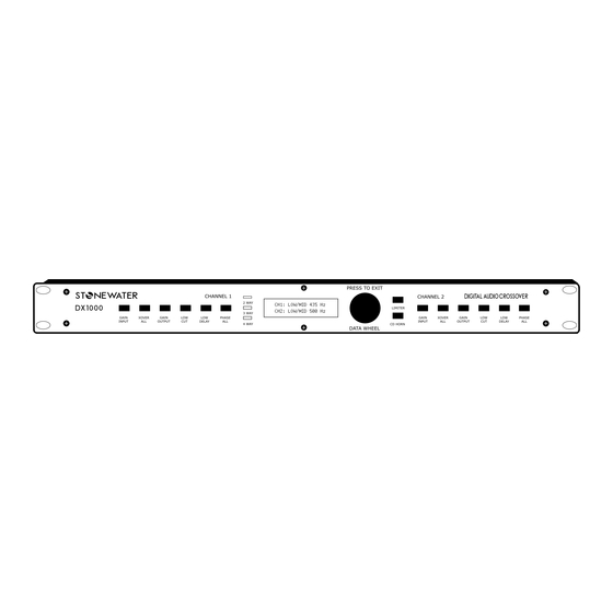
GETTING STARTED Make sure the rear panel switches are set according to the desired MODE of operation and control lock button is not engaged. Plug the AC power cord (provide with the unit) to the AC power input socket on the rear panel as shown above and turn ON the unit. The glow buttons on front panel will light up for few seconds fl... - Page 10 OPERATING THE DX1000 Below shown is the front panel of DX1000 1&6 – Both channels have their individual set of buttons to control parameters (Note when in 4 way mode operation Channel 2 button won’t allow to select parameters) 2 – LEDs to indicate the operational mode.
-
Page 12: Operational Examples
OPERATIONAL EXAMPLES nput This button helps to set the input signal gain for a specifi c channel This button helps to set the input signal gain for a specifi c channel 1: Press the button ‘GAIN INPUT’ of channel 1 or channel 2 (if in 4way mode the channel 2 ‘GAIN INPUT’... - Page 13 Over This button helps user to change the crossover frequencies for various This button helps user to change the crossover frequencies for various modes. The options available will depend on device operational mode. 2 WAY : Low/High Frequency. 3 WAY : Low/Mid Frequency, Mid/High Frequency. 4 WAY : Low/Low-Mid Frequency, Low-Mid/High-Mid frequency, High-mid/High frequency.
- Page 14 3: Again press the XOVER ALL button and the LCD display will take you to next option. Then follow STEP 2 to change the crossover point. Mid/High freq 900 Hz 4: Again press the XOVER ALL button, since there are no more crossover points to be changed in 3 WAY mode the LCD will go back to the input level display.
- Page 15 utput This button will enable the user to change the output gain for Low, Mid and This button will enable the user to change the output gain for Low, Mid and High outputs for the respective channel. 1 : Press the ‘Gain Output’ button and the button will lit up. The gain options provided by the system depends on the mode selection of the unit.
- Page 16 3 : Press the ‘Gain Output’ button again to access the next parameter option HIGH OUTPUT and follow STEP 2. Ch1 High Output -06dB 4 : Press the ‘Gain Output’ button or ‘DATA WHEEL’ to exit or press any other parameter button. The ‘Gain Output’ button will stop glowing.
- Page 17 This activates a low cut fi lter with center frequency at 40Hz which is applied to the respective input channel. Once pressed the glow button will lit up and the LCD display will fl ash the following message for few seconds before going back to level meter display screen.
- Page 18 eLay Low Delay parameter enables user to set the delay time for LOW OUTPUT. 1 : Press the ‘LOW DELAY’ button and the button will lit up. The LCD will display the following message. Ch1 Low Delay 1.6ms 2 : Rotate the ‘DATA WHEEL’ in order to change the time value. 3 : When done press the ‘LOW DELAY’...
- Page 19 hase This button helps to change the phase of the output signals of the This button helps to change the phase of the output signals of the respective channel. 1 : Press the ‘PHASE ALL’ button and the button will lit up. The LCD will show the parameter option based on the device operation mode.
- Page 20 ImIter The ‘LIMITER’ option enables the user to change the limiter threshold The ‘LIMITER’ option enables the user to change the limiter threshold parameter for each and every output channel based on the device operational mode. 2 WAY : Ch1 Low Threshold, Ch1 High Threshold, Ch2 Low Threshold, Ch2 High Threshold 3 WAY : Ch1 Low Threshold, Ch1 Mid Threshold, Ch1 High Threshold, Ch2 Low Threshold,...
- Page 21 If all the parameter options are exhausted then DX1000 will return to level meter display, and the ‘LIMITER’ button will stop glowing.
- Page 22 CD h This button activates the CD HORN equalizer fi lter on HIGH output of the DX1000. Press the ‘CD HORN’ button, the button will lit up and the LCD screen will fl ash the following message for few seconds. CD Horn ON The ‘CD HORN’...
- Page 24 FEATURES & O nput utput DX1000 provide input gain for two input channels ranging from -24dB to +6dB range and output gain ranging from -48dB to +12dB for each channel. 2/3/4 W rOssOver DX1000 can be operated in 2/3/4 way crossover mode and the front panel buttons’...
- Page 25 ImIter Limiters in DX1000 are of great use especially when it comes to protecting your speakers. Each output channel is provided with a limiter whose threshold can be controlled by user ranging from -24dB to 0dB. CD h CD horn equalizer helps to recover the higher frequencies lost from horn speaker’s output response.
- Page 26 Lf sum LF sum button is located at the rear panel of DX1000, when turned ON the low output of channel 1 provides the summed output of channel 1&2’s low frequencies. OntrOL The control lock button at the rear panel when engaged locks the front panel buttons and data wheel.
-
Page 27: Audio Connections
AUDIO CONNECTIONS Above shown is the section of audio input and output connectors on the rear panel of DX1000. Audio input and output connections for different modes of operation are mentioned below. 1 – Channel 1 input 2 – Low frequency output from channel 1 3 –... - Page 28 1 – Channel 1 input 2 – Low frequency output from channel 1 3 – Mid frequency output from Channel 1 4 – High frequency output from Channel 1 5 – Channel 2 input 6 – Low frequency output from channel 2 7 –...
-
Page 29: Specifications
SPECIFICATIONS rOssOver frequenCIes 2 WAY mode: Low/High: 45Hz to 9.6kHz 3 WAY mode: Low/Mid: 45Hz to 960Hz Mid/High: 450Hz to 9.6kHz 4 WAY mode: Low/Low-Mid: 45Hz to 960Hz Low-Mid/High Mid: 450Hz to 9.6kHz High-Mid/High: 450Hz to 9.6kHz nput Connector : Type: Balanced , Unbalanced (RF filter) Impedance:... - Page 30 a/D p erfOrmanCe Type: 24 bit Delta Sigma A/D Converter SNR: 99dB (Typical) Dynamic Range: 99dB (Typical) Sampling Rate: 48kHz D/a p erfOrmanCe Dynamic Range: >106dB A-weighted ystem erfOrmanCe Dynamic Range: 106dB THD+N: 0.002% Typical Frequency Response: 20 – 24kHz Processing: 32bit Floating point DSP unCtIOn...
- Page 31 OWer uppLy Operating voltage: 160 VAC 50/60Hz to 230 VAC 50/60Hz Power Consumption: 10 Watts hysical Dimensions: 1.75”H X 19”W X 6”D (4.45cm X 48.3 cm X 15.24 cm) Weight: 1.8 Kg Note: Specifications subject to change. For any additional information, please write in to reachus @ : stonewaterindia.com Note : Specifications subject to change without notice.
Need help?
Do you have a question about the DX 1000 and is the answer not in the manual?
Questions and answers