Table of Contents
Advertisement
Advertisement
Table of Contents

Related Manuals for IP Camera VANDAL DOME IP CAMERA


Summary of Contents for IP Camera VANDAL DOME IP CAMERA
-
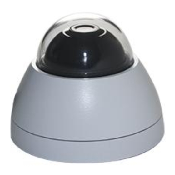
Page 1: User Manual
User Manual VANDAL DOME IP CAMERA... - Page 2 WARNING TO REDUCE THE RISK OF FIRE OR ELECTRIC SHOCK, DO NOT EXPOSE THIS PRODUCT TO RAIN OR MISTURE. DO NOT INSERT ANY METALLIC OBJECT THROUGH VENTILATION GRILLS. CAUTION CAUTION RISK OF ELECTRIC SHOCK DO NOT OPEN CAUTION:TO REDUCE THE RISK OF ELECTRIC SHOCK. DO NOT REMOVE COVER (OR BACK).
-
Page 3: Table Of Contents
Content I. PREFACE ........................ 4 II. PRODUCT SPECIFICATIONS ................4 III. PRODUCT INSTALLATION ................... 7 A. M ....................7 ONITOR ETTINGS B. H ..................8 ARDWARE NSTALLATION C. IP A ....................12 SSIGNMENT D. I ................... 16 NSTALL CTIVE CONTROL IV. -
Page 4: Preface
I. Preface This is a 1 / 4” Mega-Pixel CMOS sensor IP camera with a built-in web server. The user can view real-time video via IE browser. It supports H.264 and M-JPEG video compression, providing smooth and high video quality. The video can be stored in a Micro SD card and playback remotely. - Page 5 Flash 16MB 1 / 4” Mega-Pixel CMOS sensor Image sensor Sensitivity Color : 0.2 Lux (AGC ON) Lens Type 2.8mm @ F1.8 View Angle 77.79°(H), 49.55°(V) Power over Ethernet Audio Video Output Power Consumption DC 12V Max: 1.8W PoE Max: 2.4W Operating Temperature -10°C ~ 50°C Dimensions...
- Page 6 Triggered Action Mail, FTP, Save to SD card, Samba Password protection, IP address filtering, HTTPS Security encrypted data transmission, 802.1X port-based authentication for network protection, QoS/DSCP Firmware Upgrade HTTP mode, can be upgraded remotely Simultaneous Connection Up to 10 Micro SD card management Recording Trigger Motion Detection, IP check, Network break down (wire only),Schedule...
-
Page 7: Product Installation
III. Product Installation A. Monitor Settings Right-Click on the desktop. Select “ Properties” Change color quality to highest (32bit). -
Page 8: Hardware Installation
B. Hardware Installation 1. Placing the Camera Cable from the bottom a. Use the three screws to lock the base of camera on the ceiling or the wall. b. Put the cover back, and turn it tightly to preserve the IP. - Page 9 Cable side a. Find a conversion ring and two screws inside the accessories package. b. Use the three screws to lock the conversion ring on the ceiling or the wall. c. Use the three screws to combine the base of camera with the conversion ring.
- Page 10 2. When removing the dome cover, you will see the Micro SD card slot and the reset button. After opening the front cover, to install the IP Camera and put the cover back within 10 minutes for avoiding fog in the IP Camera Housing.
- Page 11 4. PoE (Power Over Ethernet) (Optional) 802.3af, 15.4W PoE Switch is recommended Power over Ethernet (PoE) is a technology that integrates power into a standard LAN infrastructure. It enables power to be provided to a network device, such as an IP phone or a network camera, using the same cable as that used for network connection.
-
Page 12: Ip Assignment
C. IP Assignment Use the software, “IP Installer” to assign the IP address of IP CAMERA. The software is in the attached software CD. IP installer supports two languages: IPInstallerCht.exe:Chinese version IPInstallerEng.exe:English version iii. There are 3 kinds of IP configuration. - Page 13 “Search Device” to search again. viii. Click one of the IP Camera listed on the left side. The network configuration of this IP camera will show on the right side. You may change the “name” of the IP Camera to your preference (e.g.: Office, warehouse).
- Page 14 Connection PropertiesInternet Protocol (TCP/IP) Properties Please to make sure your IP Camera and PC have the same Subnet. If not, please change IP Camera subnet or PC IP subnet accordingly. A quick way to access remote monitoring is to left-click the mouse twice on a selected IP Camera listed on “Device list”...
- Page 15 Then, please key in the default “user name: admin” and “password: admin”.
-
Page 16: Install Active Xcontrol
D. Install ActiveX control 1. For users of IE 6.0 or above: For the first time to view the camera video via IE, it will ask you to install the ActiveX component. 1. If the installation failed, please check the security setting for the IE browser. IE ... - Page 18 When popup the following dialogue box, click “Yes”. 2. You can choose another way: Go to: IE→Tools → Internet Options… → Security Tab → Trusted sites → Add the IP address and click "OK". In the site list you can key one single IP address or a LAN address. For example, if you add "192.168.21.*", all the IP address under .21 LAN will be regarded as trusted sites.
- Page 19 2. To Non-IE Web Browser Users If you use Firefox or Google chrome to access the IP camera but fail to watch the live video, please follow the steps to install necessary tools: (The following pictures are based on chrome.) a.
- Page 20 In the pop-up window, please tick the first and the third file as the picture below. Click "Next" to download both "Microsoft .NET Framework 4 Client Profile (Web Installer)" and "Microsoft Visual C++ 2010 Redistributable Package (x64)". After finishing downloading, execute the two files respectively to install them. The windows may ask you to reboot the PC when the installation is finished.
- Page 21 After finishing the downloading, execute the files to install ActiveX. Then restar t the browser. c. If you execute the steps above but still cannot see the live video normally, please try the following solution: Search for the file "np_hoem_x.dll" in your system disk. For Windows XP users, please go to "Start"...
- Page 22 install the latest ActiveX control. Start your web browser, and repeat the step 2-b: "Download the installation program which does not support IE browser" to download and install ActiveX.
-
Page 23: Live Video
IV. Live Video Start an IE browser, type the IP address of the IP camera in the address field. It will show the following dialogue box. Key-in the user name and password. The default user name and password are “admin” and “admin”. - Page 24 5. Selects the video streaming source: If the streaming 2 is closed, this function will not be displayed. 6. Shows how many people are connected to this IP camera. Double-clicking on the video will change the view to full screen mode. Press “Esc”...
- Page 25 IV. Full Screen: Full-screen mode. V. Zoom: Enable the zoom-in and zoom-out functions. First, select “Enable digital zoom” option within the pop-up dialogue box and then drag and drop the bar to adjust the zoom factors. VI. Frame Buffm Sec: This function is to build a temporary buffm to accumulate several video frames.
-
Page 26: Camera Configuration
V. Camera Configuration Click to get into the administration page. Click to go back to the live video page. -
Page 27: System
A. System I. System Information Server Information: Set up the camera name, select language, and set up the camera time. Server Name: This is the Camera name. This name will be shown on the IP Installer. Select language: English, Traditional Chinese, and Simplified Chinese can be selected. - Page 28 Server time setting: Select options to set up time - “NTP”, “Synchronize with PC’s time”, “Manual”, “The date and time remain the same”.
- Page 29 II. User Management The IP Camera supports three different users, administrator, general user, and anonymous user. a. Anonymous User Login: Select “Yes” for allowing everybody to watch live video without username and password. However, if you try to enter the configuration page the camera will ask you to key-in username and password.
- Page 30 c. Add user Type the user name and password, then click “Add/Set”. The guest user can only browse live video page and is not allowed to enter the configuration page. d. Click “edit” or “delete” in the user list to modify them. The system will ask you to key-in the password in the pop-up window before you edit the user information.
- Page 31 PC, or upgrade from previous saved settings. Settings download: Right-click the mouse button on Setting Download Select “Save AS…” to save current IP Camera settings in PC Select saving directory Save Upgrade from previous settings Browse search previous settings open upgrade ...
-
Page 32: Network
B. Network I. IP Settings IP Assignment The IP Camera supports DHCP and static IP. DHCP: The IP Camera will get all the network parameters automatically. Static IP: Type-in the IP address subnet mask, gateway, and DNS manually. - Page 33 IP camera. This virtual IPv6 address cannot be used on WAN. To use IPv6 address to access the IP camera, open the web browser, and key-in the [IPv6 address] in the address bar. The [ ] parentheses...
- Page 34 (Default: 80) HTTPs Port: setup the https port(Default: 443) UPnP This IP camera supports UPnP, if this service is enabled on your computer, the camera will automatically be detected and a new icon will be added to “My Network Places.”...
- Page 35 Note: UPnP must be enabled on your computer. Please follow the procedure to activate UPnP: <Approach 1> open the Control Panel from the Start Menu Select Add/Remove Programs Select Add/Remove Windows Components and open Networking Services section Click Details and select UPnP to setup the service The IP device icon will be added to “MY Network Places”...
- Page 36 4. Now the IP device is displayed under the LAN. Double-click the icon to access the camera via web browser. T o disable the UPnP , click "Hide icons for networked UPnP devises" in the tasks column.
- Page 37 RTSP setting If you have a media player that supports RTSP protocol, you can use it to receive the video streaming from IP camera. The RTSP address can be set for two streamings respectively. Please jump to RTSP Server: enable or disable "Disable"...
- Page 38 Multicast Setting (Based on the RTSP Server) Multicast is a bandwidth conservation technology. This function allows several users to share the same packet sent from the IP camera. For using Multicast, appoint here an IP Address and port. TTL means the life time of packet, the larger the value is, the more users can receive the packet.
- Page 39 ONVIF is still connected. If the connection has been broken, the camera will stop transmitting video to the user. Bonjour This function allows MAC systems to connect to this IP camera. On “Bonjour Name” Key-in the name here.
- Page 40 The web browser "Safari" also has a Bonjour function. Tick "Include Bonjour" in the bookmark setting, for the IP camera to appear under the bonjour category. Click the icon to connect to the IP camera. So far the Bonjour function on Safari browser doesn't support HTTPS protocol.
- Page 41 If your PC supports LLTD, enable this function for allowing checking the connection status, properties, and device location (IP address) in the network map. If the computer is running Windows Vista or Windows 7, you can find LLTD through the path: Control Panel →...
- Page 42 You can select the connection type. • Http: the user can access the camera via the Http path but cannot access it via the Https path. • Https: the user can access the camera via the Https path but cannot access it via the Http path. •...
- Page 43 Certificate generation process: Remove the existing certificate: Before you generate a new certificate, please remove the installed one. Select "Http" connection type and click "Remove". If a dialog box pops up to ask you to confirm, click “Yes”. Created Request: Fill-in the following form and click “apply”.
- Page 44 After generating a certificate request, if you choose to turn it and verified by a trusted third-party, click “Content” and copy all the request content. According to the certificate source, there are two ways to install the certificate: If you had sent the certificate request for signing and receiving a signed certificate, click ”...
- Page 45 If you choose to generate a self-signed certificate, fill-in the following forms and set the validity day, click “Apply” to finish installed it. After finishing the installation, you can click “Content” to call out and check the certificate content. To use Https to access the camera, open your browser, and key-in "https:// (IP address)/"...
- Page 46 Meaning that certificate is self-signed or signed by a Click “Proceed anyway” distrusted institution. continuing to the camera page. b. SNMP (Simple Network Management Protocol) 1. Enable SNMPv1 or SNMPv2 and write the name of both Write Community and Read Community. 2.
- Page 47 3. Enable SNMPv1/SNMPv2 Trap for detecting the Trap server. Please set what event needs to be detected. • Cold Start: The camera starts up or reboots. • Setting changed: The SNMP settings has been changed. • Network Disconnected: The network connection was broken down.
- Page 48 community) • SD Insert / Remove: A Micro SD card is inserted or removed. c. Access list: ”Enable IP address filter” for setting the IP addresses which allows or denies this camera. There are two options, single and range. QoS/DSCP(Quality Server/Differentiated Services Code-point):...
- Page 49 DSCP specifies a simple mechanism for classifying and managing network traffic and provide QoS on IP networks. DSCP is a 6-bit in the IP header for packet classification purpose. Please define it for Live Stream, Event / Alarm and Management. IEEE 802.1x: IEEE 802.1x is an IEEE standard for port-based Network Access Control.
- Page 50 III. PPPoE & DDNS: PPPoE: Select “Enabled” to use PPPoE. Key-in Username and password for ADSL connection. Send mail after dialed: When connect to the internet, it will send a mail to a specific mail account. For mail setting, please refer to “Mail and FTP” settings.
- Page 51 DDNS: It supports DDNS (Dynamic DNS) service. DynDNS: (1) Enable this service (2) Key-in the DynDNS server name, user name, and password. (3) Set up the IP Schedule update refreshing rate. (4) Click “Apply”...
- Page 52 (5) If the schedule update is too frequently, the IP may be blocked. In general, schedule update every day (1440 minutes) is recommended Camddns service: Please enable this service Key-in user name. IP schedule update default at 5 minutes Click “Apply”. DDNS Status (1) Updating: Information update...
- Page 53 (2) Idle: Stop service (3) DDNS registration successful, http://<username>.ddns.camddns.com: Register successfully. (4) Update Failed, the name is already registered: The user name has already been used. Please change it. (5) Update Failed; please check your internet connection: Network connection failed. (6) Update Failed, please check the account information you provided: The server, user name, and password may be wrong.
- Page 54 To send out the video via mail of FTP, please set up the configuration first.
- Page 55 Samba Select this option to send the media files via a neighbor network when an event is triggered. Click “Apply” to save the setting, then use “Test” button to test the server connection. A message box will tell you “OK!” if it works, and a test document will be created in the location.
-
Page 56: A/V Setting
C. A/V Setting 1. Image Setting For security and privacy purposes, there are three areas that can be set up for privacy. Click the Area button first, and then drag an area on the above image. Remember to save your settings. The masked area will not shown on both live view and recording image. - Page 57 lighting. Enable this function for getting brighter image on low light, but the level of noise may also increase. The available values are: 8x, 16x, 24x, 32x C. Shutter Time: Choose the location of your camera or a fixed shutter time.
- Page 58 E. D-WDR: This function enables the camera to reduce the contrast in the view to avoid dark zones as a result of over and under exposure. If the Input resolution is 30fps, the default value is fixed on ENABLED. The available values are: OFF, 1, 2, 3, 4, 5, 6, 7, 8 If the D-WDR is enabled the values for bright, dark and contrast can be adjusted.
- Page 59 Video System: PAL & NTSC Corridor Mode: none, 90 degree, 270 degree Streaming 1 & 2 Basic Mode: (Max Video Frame Rate for both streaming combined is 30 FPS) Resolution: 1280x800@30fps, 1280x720@30fps, 640x480@30fps, 320x240@30fps, 176x144@30fps Profile Chose between Main or Baseline Quality There are 5 levels: Best/ High/ Standard/ Medium/ Low...
- Page 60 The higher the quality is, the bigger the file size is. Not good for internet transmission. Video Frame Rate (5~30 FPS): The video refreshing rate per second. Video Format: H.264 or JPEG RTSP Path: RTSP output name Streaming 1 & 2 Advanced Mode: Resolution 1280x800@30fps,1280x720@30fps, 640x480@30fps, 320x240@30fps, 176x144@30fps...
- Page 61 Bitrate Control Mode There are CBR (Constant Bit Rate) and VBR (Variable Bit Rate) CBR: 32Kbps~8Mbps (the higher the CBR is, the better the video quality is) VBR: 1(Low) ~10(High) – Compression rate, the higher the compression rate, the lower the picture quality is; vise versa. The balance between VBR and network bandwidth will affect the picture quality.
- Page 62 Resolution: 640x480@15fps, 320x240@15fps, 176x144@15fps Video Bitrate: 32Kbps~1Mbps (the higher Video Bitrate is, the better the video quality is) Video Frame Rate The video refreshing rate per second. RTSP Path: RTSP output name...
-
Page 63: Event List
D. Event List The IP Cam provides multiple event settings. 1. Event Setting a. Motion Detection To enable motion detection, please tick "Area 1/2/3". Click "Area 1/2/3" in “Area Setting”, and draw an area on the preview screen. When motion is detected in the area, the word "Motion!"... - Page 64 and action is triggered, it cannot be triggered again within 10 seconds. • Based on the schedule: When the option box is ticked, only during the selected schedule time the motion detection is enabled. b. Tampering Detection When the camera view is covered, moved, hit by strong light, or out of focus, the tampering detection will be triggered, and send snapshot or video to mail/FTP/Samba/SD card, or trigger the external alarm.
- Page 65 Before Tampering Detection Tampering Triggered (Glare) Before Tampering Detection Tampering Triggered (Camera Moved) • Interval: The tampering detecting interval. Take the diagram below as example. The interval is set for 30 second; the camera lens is covered during 10 - 40 sec. At time point B, the camera compares the view with time point A, and sends an alarm when it founds that the lens is covered.
- Page 66 Record Time Setting When an event occurs, the IP camera can record a video clip or take a snapshot, and then send it via mail/ FTP/ Samba. Select the video recording length before and after the event is detected.
- Page 67 SD card after the IP Camera detects network dis-connected, if set “Save to SD card”. f. Network IP check: After enable IP Check, the IP camera can check if the network server is connecting. If the IP camera checking failed, the image will be recorded to the SD card.
- Page 68 2. Schedule a. Schedule: After complete the schedule setup, the camera data will be recorded according to the schedule setup. b. Snapshot: After enable the snapshot function; the user can select the storage position of the snapshot file, the interval time of the snapshot and the reserved file name of the snapshot.
- Page 69 a. Input Setting: The IP Cam supports input and output. When the input condition is triggered, it can trigger the relay; send the video to mail addresses /FTP server / SAMBA. • Interval: For example, if you select "10 sec" here, once the motion is detected and action is triggered, it cannot be triggered again within 10 seconds.
- Page 70 b. Output Setting: The output mode affects the DO or relay out duration. ON/Off Switch: The camera triggers the external device and lasts for 10 seconds. You can turn off the alarm manually by clicking “off” at the right bottom of the live video page. ...
- Page 71 5. Log List a. Playback Please Insert t h e Micro SD card before use it. Make sure t o push the Micro SD card into the slot completely. Click the date listed on this page for showing the video list. The video format is AVI.
- Page 72 You can insert the Micro SD card to the PC and read the files directly, or use FlashGet instead to download the files from the IP camera. (In this way you do not need to pull out the Micro SD card from the camera.)
- Page 73 (i) Enter data list and right-click “Files link daily”, select “save target as…” then save the link list to PC. (ii) Open FlashGet, select "File" → "Import" → "Import list", and find the link list file you just saved. The file name may be called “SD_list”. (iii) FlashGet will show you the link list, and you can tick the files you want to copy to your PC.
-
Page 74: Network Configuration
Internet Access: ADSL or Cable Modem IP address: One real IP or one dynamic IP Only the IP CAMERA is connected to the internet For fixed real IP, set up the IP into IP CAMERA. For dynamic IP, start PPPoE. - Page 75 IP address: More than one real IP or one dynamic IP IP CAMERA and PC connect to the internet Device needed: Switch Hub For fixed real IP, set up the IP into IP CAMERA and PC. For dynamic IP, start PPPoE. III. Configuration 3:...
-
Page 76: Factory Default
VII. Factory Default If you forget your password, please follow the steps to revert back to default value. • Remove power adapter and Ethernet cable from the camera. • Press and hold the Default button on the back of the camera, as the picture. •... -
Page 77: Universal Password
Note: Universal password will be valid only when you enable the function in User Management. 1. First, you need to know the IP address and MAC of your IP camera. You can use IP installer to scan the LAN, and see the IP address and MAC on the side column. - Page 78 3. Key in the camera IP address “IP Adder.” column and MAC in “MAC” column, and then click “encoder”. You will see a set of username and password appear, as below: The universal username and password are generated from the IP address and MAC you key in, so if you change the camera IP address the universal password changes, too.
- Page 79 5. Now you can login as administrator. Turn to User Management page. The use of universal password does not affect the previous user setting, so the administrator account password does not change until you edit it. Please click “Edit” to give a new administrator password.
-
Page 80: Package Contents
IX. Package contents IP Camera Adaptor Quick Installation Guide RJ45 Female to Female Screws x3 Wall Plug x3 Conversion Ring + Screws x6 • The CD includes user manual and software tools • Adaptor: AC100-240V DC12V/0.5A... -
Page 81: Micro Sd Card Compatibility
X. Micro SD Card Compatibility The following are the recommended Micro SD Cards: SDHC class4 16GB SDHC class4 32GB class4 16GB class4 32GB SDHC class6 Transcend SDHC class6 SDHC class6 16GB class6 class6 class6 16GB SDHC class4 SDHC class10 SanDisk SDHC class4 SDHC...
Need help?
Do you have a question about the VANDAL DOME IP CAMERA and is the answer not in the manual?
Questions and answers