Table of Contents
Advertisement
Quick Links
CHANNEL SAFETY SYSTEMS
i
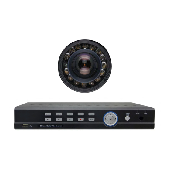
The complete professional CCTV kit
CHANNEL SAFETY SYSTEMS
Petersfield Business Park
Bedford Road
Petersfield
Hampshire
GU32 3QA
DIGITAL VIDEO RECORDER (DVR) USER'S MANUAL
DVR USER MANUAL
from Channel Safety Systems
t: 0845 884 7000 | w: www.channelsafety.co.uk
™
t: 0845 884 7000
f: 0845 884 6000
e: sales@channelsafety.co.uk
w: www.channelsafety.co.uk
| 1/1
Advertisement
Table of Contents

Subscribe to Our Youtube Channel
Summary of Contents for Channel iCapture
- Page 1 CHANNEL SAFETY SYSTEMS t: 0845 884 7000 | w: www.channelsafety.co.uk ™ The complete professional CCTV kit from Channel Safety Systems CHANNEL SAFETY SYSTEMS t: 0845 884 7000 Petersfield Business Park f: 0845 884 6000 Bedford Road Petersfield Hampshire e: sales@channelsafety.co.uk GU32 3QA w: www.channelsafety.co.uk...
-
Page 2: Table Of Contents
CHANNEL SAFETY SYSTEMS t: 0845 884 7000 | w: www.channelsafety.co.uk CONTENTS Safety Instructions ..................... 5 Chapter 1: Features ................... 6 Chapter 2: Overview ..................7 3.1. Front Panel ....................7 3.1.1 8CH CIF DVR Front Panel ............... 7 3.1.2 16CH-CIF DVR Front Panel ..............8 3.2. - Page 3 CHANNEL SAFETY SYSTEMS t: 0845 884 7000 | w: www.channelsafety.co.uk CONTENTS CONTINUED..6.3.15 Network: Network set ................27 6.3.16 Router’s Port Forwarding ...............27 6.3.17 Sub Stream ....................27 6.3.18 Email Set ....................28 6.3.19 Mobile Set ....................28 6.3.20 DDNS Set ....................29 6.3.21 Alarm: Motion ..................29 6.3.22...
- Page 4 CHANNEL SAFETY SYSTEMS t: 0845 884 7000 | w: www.channelsafety.co.uk CONTENTS CONTINUED..7.3.10 Record ....................50 7.3.11 Network Parameters .................51-52 7.3.12 Alarm Set ....................53 7.3.13 Device ......................54 7.3.14 System ....................55-56 7.3.14 Advanced ...................57-59 7.3.15 Local Setting ...................60 7.3.16 Logout .....................60 Chapter 7: Appendix ..................61 Operation Function Table ..............
-
Page 5: Safety Instructions
CHANNEL SAFETY SYSTEMS t: 0845 884 7000 | w: www.channelsafety.co.uk SAFETY INSTRUCTIONS Please read all the safety instructions and user manual before the equipment is operated. Power sources This equipment should be operated only from the type of power source indicated on the marking label. If you are not sure of the type of power, please consult your supplier. -
Page 6: Chapter 1: Features
CHANNEL SAFETY SYSTEMS t: 0845 884 7000 | w: www.channelsafety.co.uk CHAPTER 1: FEATURES Function Brief and Description Double video output; with monitor, VGA virtual out- put port or HDMI Output; Support net-viewer and MP Real time monitoring live surveillance and also support zoom in/out, auto sequence and PIP display. -
Page 7: Chapter 2: Overview
IR Receiver Receives IR signal from Remote Controller SEARCH Record search MUTE Mute on/off Switch to previous channel Switch to next channel On live mode, clicking the button will switch to Quad display. Up key Move up menu Enter menu, select Power Indicator If the “Green”... -
Page 8: 16Ch-Cif Dvr Front Panel
CHANNEL SAFETY SYSTEMS t: 0845 884 7000 | w: www.channelsafety.co.uk 3.1.2 16CH CIF DVR Front Panel Key title or Item Type Function & Description Indicator When the “Red” indicator flashes it means the hard drive is being HDD indicator read or written to. -
Page 9: Rear Panel
CHANNEL SAFETY SYSTEMS t: 0845 884 7000 | w: www.channelsafety.co.uk Rear Panel 3.2.1 8CH CIF DVR Rear Panel Item Physical port Function & Description Video input Connect CH1-16 (Virtual) video input(BNC interface( Video output (UP) Main video output; (Down) Spot output (BNC interface) -
Page 10: 16Ch-Cif Dvr Rear Panel
RS485/Sensor/Alarm port functions: Alarm input: Connect [-] port of your sensor to G (GND) pin, and [+] port to channel input according to the alarm device you purchased. Alarm output: Connect to the two ports marked with “out” PTZ Port-Connect your camera to RS-485A and RS485B accordingly. -
Page 11: 8-Ch Remote Controller
CHANNEL SAFETY SYSTEMS t: 0845 884 7000 | w: www.channelsafety.co.uk 8-CH Remote Controller Item Key function Channel select 1-8; Numeric key Numeric key; Clicking numeric “0” allow you switch to GUI (Graphical user Interface) function Multiple display mode Enter into Main menu/Exit... -
Page 12: 16-Ch Remote Controller
3×3 Enter into 9-split display 4×4 Enter into 16-split display AUTO Enter into dwell time display Channel select; numeric key Multiple CH display (Quad, 9-split, 16-split and full screen DISPLAY MODE display( Up direction key Down direction key Left/right direction key; also decrease/increase parameter ◀... -
Page 13: Mouse Operation
CHANNEL SAFETY SYSTEMS t: 0845 884 7000 | w: www.channelsafety.co.uk Mouse Operation Alongside using the buttons of the front panel of your DVR or remote controller, you can also use the mouse to perform system operations. Type Function In menu lock mode, Enter into pop-up menu and clicking any sub menu to pop up Log-in window;... -
Page 14: Chapter 3: Dvr Installation
CHANNEL SAFETY SYSTEMS t: 0845 884 7000 | w: www.channelsafety.co.uk CHAPTER 3: DVR INSTALLATION HDD Installation (Applicable to the model with HDD drawer) Caution: Please do not install or take out hard drive when CVR is running! (1) The model has a HDD drawer. Please use provide key to take out the HDD drawer and put HDD into the drawer correctly. -
Page 15: Chapter 4: Dvr Boot Up
Pop-up menu. Note: When internal HDD is not connected or an error occurs, the character “H” will appear on the first channel of the live screen and accompany buzzer alarm. If you want to close the buzzer alarm, please enter into [Main menu Alarm] to set HDD loss, HDD space not enough and alarm output to “off”... -
Page 16: Chapter 5: Dvr Menu
CHANNEL SAFETY SYSTEMS t: 0845 884 7000 | w: www.channelsafety.co.uk CHAPTER 5: DVR MENU 6.1 Pop-up Menu After finishing system initialization, right click your mouse on the main interface mode to enter into the Pop-up Menu. Now you can complete the perform parameter setting and operate on Main Menu, Multi-Pics, PTZ, PIP, Rec. -
Page 17: Main Menu Guide
CHANNEL SAFETY SYSTEMS t: 0845 884 7000 | w: www.channelsafety.co.uk 6.2 Main Menu Guide DVR USER MANUAL | 1/17... -
Page 18: Main Menu
When set to “Enable”, you can record the system time into the record history. Copy: allows you to copy all data from one channel to an other. Picture 6-4 shows the Colour Menu where you can adjust image brightness, saturation, contrast and hue parameters of each channel. -
Page 19: Output Mode
Go to [Main menu-Display-Output] to enter into Click [Live] to pop up the interface shown as in the output set interface as shown in Picture 6-5. Picture 6-6. Now you can perform the channel sequence setting. Picture 6-6 Picture 6-5... -
Page 20: Privacy Zone
6.3.3 Privacy Zone This function allows you to setup the privacy zone parameters according to Picture 6-12. Each channel can be set up to four privacy zones. Please follow the steps below to setup: Select the area no (Area 1 ~ Area 4);... -
Page 21: Record Set: Record Parameters
Schedule Click [Main Menu-Record-Schedule] to enter into the interface shown as Picture 6-15. [Channel] option allows you to select the channel you desire. To setup weekly schedules, tick-select the box of the record status you want (Alarm, General, or No Record) and then click on each box in the schedule time line that you want this method applied to. -
Page 22: Main Stream
6.3.7 Search: Record Search Click [Main Menu-Search-Record Search] to enter into the interface shown as Picture 6-17 Channel: allows you to select the channel(s) you desire to search. Date Search: In the Video Search screen, users can search for records in a specific date. To execute a video search, high- light and select the numeric date field, then click a detailed time frame of the specific date. -
Page 23: Channel Select
Click [Main Menu-Search-Event Search] to enter into the interface shown in Picture 6-20. You can highlight and double-click the desired record for playback. You can also can filter the records you want to view based on date, time, channel and record mode search. (First Page): Goes to the first page on the list. -
Page 24: File Backup
CHANNEL SAFETY SYSTEMS t: 0845 884 7000 | w: www.channelsafety.co.uk 6.3.10 File Backup You can backup the recorded files based on event or time. 6.3.11 File Backup: File Based On Event In the [File List] mode, if you wish to backup records, tick-select the BAK check-boxes which correspond to the records you... -
Page 25: File Backup File Based On Time
CHANNEL SAFETY SYSTEMS t: 0845 884 7000 | w: www.channelsafety.co.uk 6.3.12 File Backup File Based On Time You can also allow back-up record files based on time. Please follow the steps below to back up these files (Details operations please refer to section ): Input start time and end time on the time edit box;... - Page 26 CHANNEL SAFETY SYSTEMS t: 0845 884 7000 | w: www.channelsafety.co.uk Slow button: click the icon to play the backup record at 1/2, 1/4, 1/8 and 1/16 speed. FF button: click the icon to fast forward the backup record at x2, x4, x8 and/or x16 speed.
-
Page 27: Log Search
CHANNEL SAFETY SYSTEMS t: 0845 884 7000 | w: www.channelsafety.co.uk 6.3.14 Log Search Go to [Main menu-Search-Log] option to enter into the Log search interface shown in Picture 6-25. Here you can preview the log information you have searched. Click [Backup] to export all the log information which is... - Page 28 CHANNEL SAFETY SYSTEMS t: 0845 884 7000 | w: www.channelsafety.co.uk When selecting DHCP from the Type, A router will automatically allocate IP address for your DVR. After restarting each time, the IP address captured by your DVR may be different. So, port forwarding is required when you visit a remote DVR.
-
Page 29: Router's Port Forwarding
CHANNEL SAFETY SYSTEMS t: 0845 884 7000 | w: www.channelsafety.co.uk 6.3.16 Router’s Port Forwarding Port forwarding is required when you want to access the DVR connected to the router from outside of the router’s If PPPoE is selected, port forwarding is not required. -
Page 30: Email Set
CHANNEL SAFETY SYSTEMS t: 0845 884 7000 | w: www.channelsafety.co.uk 6.3.18 Email Set Click [Main Menu-Network-Email] option to enter into the email set interface shown as Picture 6-33 SSL: is a security link transport protocol. You can encrypt your communication info (including your email) using SSL to prevent hackers from monitoring your email or communication info and even your password. -
Page 31: Ddns Set
CHANNEL SAFETY SYSTEMS t: 0845 884 7000 | w: www.channelsafety.co.uk 6.3.20 DDNS Set DDNS (Dynamic DNS) is a service that registers a domain name and the floating IP address with the DDNS server so that the domain name can be routed to the IP address; even if the IP address is changed in a dynamic IP system. -
Page 32: Alarm Set
CHANNEL SAFETY SYSTEMS t: 0845 884 7000 | w: www.channelsafety.co.uk Full screen Alarm: The function is defaulted to “On”. When the motion is detected, the corresponding channel will be switched to the full screen mode. Record Channel: the record channel will be activated when the motion is detected. -
Page 33: Device: Hard Disk Drive Set
CHANNEL SAFETY SYSTEMS t: 0845 884 7000 | w: www.channelsafety.co.uk Alarm Type Function Sends an alarm when the DVR can’t receive video signals (such as, camera Video Loss damage, a cable is broken or damaged or there is a power supply malfunction). -
Page 34: Ptz Set
This figure is only for D9016 / CIF model reference You can select the channel you desire to control and set PTZ protocol (Pelco-D or Pelco-P), Baud Rate (1200, 2400, 4800, 9600), Data bit (8, 7, 6, 5), Stop bit (1, 2), Parity Check (None, Odd, Even, Mark, Space), Address Code and Cruise status respectively. -
Page 35: Serial Set
CHANNEL SAFETY SYSTEMS t: 0845 884 7000 | w: www.channelsafety.co.uk 6.3.25 Serial Set Enter into the [Main menu-Device-Serial] Menu shown in Picture 6-45 To operate the DVR via a keyboard, it is required to set the communication protocol. Baud rate: set baud rate of serial communication. -
Page 36: Network Time Protocol (Ntp) Service
CHANNEL SAFETY SYSTEMS t: 0845 884 7000 | w: www.channelsafety.co.uk 6.3.28 Network Time Protocol (NTP) Service Click [Main menu-System-General] to enter into the menu shown as Picture 6-48 NTP Service: Allows you to enable/disable the NTP function. Server Address: currently supports pool.ntp.org. - Page 37 Playback: Tick-select the option and the user is allowed to playback the recording you selected. PTZ control: Tick-select the option and the user is allowed to perform the PTZ operation for the selected channel. DVR USER MANUAL | 1/37...
-
Page 38: Information
CHANNEL SAFETY SYSTEMS t: 0845 884 7000 | w: www.channelsafety.co.uk 6.3.30 Information Click [Main Menu-System-Info] and then enter into the menu shown in Picture 6-52 Her users can check the current Device name, Device ID, Device type, Device S/N, MAC address, IE version, Software version, Panel version etc. -
Page 39: Event
CHANNEL SAFETY SYSTEMS t: 0845 884 7000 | w: www.channelsafety.co.uk 6.11.2 Event Click [Main menu-Advanced-Events] to enter into the <Events> menu shown in Picture 6-54 Event Type: support the three abnormal types: Disk No Space, Disk Error and Video Loss. -
Page 40: Ptz Control
Cruise Set Open auto cruise function on the PTZ setting menu if you want to setup cruise function (system default: off), and set up cruise channel, cur point and total quantity and stop time etc How to set pre-set point... -
Page 41: Pip Mode
CHANNEL SAFETY SYSTEMS t: 0845 884 7000 | w: www.channelsafety.co.uk PIP Mode You can display a Picture-in-Picture in live mode. PIP has two display modes, including 1X1 display mode and 1X2 display mode, as shown below. 1x1 display mode 1x2 display mode... -
Page 42: Chapter 6: Web Application Manager
CHANNEL SAFETY SYSTEMS t: 0845 884 7000 | w: www.channelsafety.co.uk CHAPTER 6: WEB APPLICATION MANAGER 7.1 Plug-in Download and Installation Open your web browser and input the IP address and web port of DVR, for example:http://172.18.6.202:8080/ . If your computer is connected to internet, it will download and install “ActiveX” Plug-in automatically. If your computer system is Vista, you may need to setup the user authority. -
Page 43: Web Application Manager Log-In
CHANNEL SAFETY SYSTEMS t: 0845 884 7000 | w: www.channelsafety.co.uk Web Application Manager Log-in After plug-in installation, please input your user name, password and client port number; and select <Main stream> or <sub stream>, and then tick-select <Open All Channels Preview>;... -
Page 44: Live Display
The image should be saved as *.BMP file format. By clicking the icon this will close/open the current channel’s live mode Or you can click on any <Live> window to get the menu as shown in Picture 7-4 Show bit rate: show current bit rate;... -
Page 45: Ptz Control
CHANNEL SAFETY SYSTEMS t: 0845 884 7000 | w: www.channelsafety.co.uk 7.3.3 PTZ Control PTZ moving Direction control: allows you to control the PTZ camera direction. And the middle button is called [Auto-cruise] button. PTZ speed control bar Iris, Focus and Zoom control Preset setting/clear;... -
Page 46: Record Search
(original part green) stands for no record during this period Picture 7-9 If you tick-select the synchronised option, that means the selected channel will playback simultaneously; alternatively, you can separately control the channels playback. Thirdly, Click [ ] icon to start the record playback. -
Page 47: Playback Control
Record clip file will be saved as *.264 format. Snapshot function Move the mouse cursor to the channel you want to capture, and click [ ] icon to capture the live images remotely. After capturing the images successfully, you are allowed to save it to a specified location, as shown in Picture 7-11. - Page 48 CHANNEL SAFETY SYSTEMS t: 0845 884 7000 | w: www.channelsafety.co.uk Picture 7-11 Record file download Click the [ ] icon to enter into the menu shown in Picture 7-12. Picture 7-12 Tick-select the record files you want to download and click [Start download] The System will download the record files in turn and save to local PC.
-
Page 49: Configuration
Picture 7-13 Privacy zone: Each channel could be set up to four privacy zones as shown in Picture 7-14 below. For details of parameters please refer to section Privacy Zone. If you want to delete a privacy zone, please firstly select one zone, and then click the <Clear>... -
Page 50: Record
Picture 7-16 Main Stream: Detailed settings please refer to DVR local setting. Here users can modify the resolution, frame rate, Bit rate and audio of the record channel. See Pictures 7-17 on the next page. DVR USER MANUAL | 1/50... -
Page 51: Network Parameters
CHANNEL SAFETY SYSTEMS t: 0845 884 7000 | w: www.channelsafety.co.uk Picture 7-17 This figure is only for D9016 / CIF model reference 7.3.11 Network Parameters Select <Network> option to navigate to it’s sub-options: Network, sub stream, Email, mobile and DDNS configu- ration. - Page 52 CHANNEL SAFETY SYSTEMS t: 0845 884 7000 | w: www.channelsafety.co.uk Picture 7-19 Set network type to “PPPoE” shown in Picture 7-20 below. Its user name and password should be consistent with the DVR local setting Picture 7-20 Sub stream (shown in Picture 7-21 on the next page): Relative parameters should be consistent with the DVR local settings.
- Page 53 CHANNEL SAFETY SYSTEMS t: 0845 884 7000 | w: www.channelsafety.co.uk Picture 7-21 Email setting: Click on [Email setting] to allow you to set the alarm email configuration parameters shown in Picture 7-22 below. Detailed parameters should be consistent with the DVR local setting...
- Page 54 CHANNEL SAFETY SYSTEMS t: 0845 884 7000 | w: www.channelsafety.co.uk Picture 7-23 DDNS Setting: After the user applies for a DDNS service shown in Picture 7-24 below, you can enable <DDNS> function under any one network type mode (Static, DHCP and PPPoE). Now you remotely visit the DVR through the domain name (http://domain name: port No).
-
Page 55: Alarm Set
CHANNEL SAFETY SYSTEMS t: 0845 884 7000 | w: www.channelsafety.co.uk 7.3.12 Alarm Set Click <Alarm> option to navigate to its sub-options: Motion, I/O Alarm shown in Picture 7-25 below. Picture 7-25 Motion Detection: allows you to configure its <Sensitivity>, <Alarm out>, <Alarm record> and <Alarm Capture>... -
Page 56: Device
CHANNEL SAFETY SYSTEMS t: 0845 884 7000 | w: www.channelsafety.co.uk Picture 7-27 7.3.13 Device Click <Device> to navigate to its sub-options: HDD and PTZ. HDD: allows you to check out HDD status and overwritten time shown in Picture 7-28 (On the next page). -
Page 57: System
CHANNEL SAFETY SYSTEMS t: 0845 884 7000 | w: www.channelsafety.co.uk Picture 7-29 7.3.13 System Click <System> option to navigate to its sub-options: General, Users and information. General: Users could check the DVR’s language and video system, and also set the system time, date format, DST and NTP shown in Picture 7-30 below. - Page 58 CHANNEL SAFETY SYSTEMS t: 0845 884 7000 | w: www.channelsafety.co.uk Picture 7-31 Information: Allows you to check the device name, number, type, MAC address, software version, IE version and hardware version shown in Picture 7-32 below. Picture 7-32 DVR USER MANUAL...
-
Page 59: Advanced
CHANNEL SAFETY SYSTEMS t: 0845 884 7000 | w: www.channelsafety.co.uk 7.3.14 Advanced Click <Advanced> to navigate to its sub-options: System update, Load default, Events and system maintain etc. System Update: allows you to upgrade the DVR system remotely shown in Picture 7-33 below. - Page 60 CHANNEL SAFETY SYSTEMS t: 0845 884 7000 | w: www.channelsafety.co.uk Picture 7-35 Load Default: allows you to recover the defaulted parameters of the DVR remotely shown in Picture 7-36. Settings should be consistent with the DVR local settings Picture 7-36...
- Page 61 CHANNEL SAFETY SYSTEMS t: 0845 884 7000 | w: www.channelsafety.co.uk Picture 7-37 Maintain: allows you to set the auto system maintain for the DVR remotely shown in Picture 7-38 below. Settings should be consistent with the DVR local setting. Picture 7-38...
-
Page 62: Local Setting
CHANNEL SAFETY SYSTEMS t: 0845 884 7000 | w: www.channelsafety.co.uk 7.3.15 Local Setting Under the <Local setting> option, users can set the record path of record file (Live record and Playback clip file), download path of remote file, Snapshot path, File type (H.264 and AVI) and Internal shown in Picture 7-39 below. -
Page 63: Chapter 7: Appendix
On/ Off. Set image quality, resolu- Record setting tion, volume, record mode an pack time Time based search, channel Basic Setting Record search based search and rec. mode based search. Specified time playback, Record Playback... -
Page 64: Motion Detection
CHANNEL SAFETY SYSTEMS t: 0845 884 7000 | w: www.channelsafety.co.uk User password Set or modify user password Set HDD loss, HDD space, video loss, I/O status, alarm Alarm setting management and Email alarm notifications Set on/off status of MD; Motion detection select sensitivity and set mo- tion detection area. -
Page 65: Mobile Monitor
CHANNEL SAFETY SYSTEMS t: 0845 884 7000 | w: www.channelsafety.co.uk Check device ID, software System info version and MAC address Auxiliary Function In addition to illustrating picture, Parenthesis gener- (( ally indicate optional param- eter value of previous menu. Clicking the button will save Enter current parameter. -
Page 66: Record Alarm Setting
CHANNEL SAFETY SYSTEMS t: 0845 884 7000 | w: www.channelsafety.co.uk 8.2 Record Alarm Settings Please refer the below matrix: “” stands for “only alarm but no record”; “AMR” stands for “alarm record”; “NLR” stand for “normal record”; and “NOR” stand for “ no record”. -
Page 67: Troubleshooting
CHANNEL SAFETY SYSTEMS t: 0845 884 7000 | w: www.channelsafety.co.uk 8.4 Troubleshooting Q: What can I do if the system does not detect the HDD? A: Check if the power supply system is properly connected and the data cord and power cables are se- curely connected Q: We have changed the password but can’t remember the new password, how can we access the system? -
Page 68: System Connection Diagram
CHANNEL SAFETY SYSTEMS t: 0845 884 7000 | w: www.channelsafety.co.uk 8.6 System Connection Diagram 8-CH-CIF 16-CH CIF DVR USER MANUAL | 1/68... -
Page 69: Accessories
CHANNEL SAFETY SYSTEMS t: 0845 884 7000 | w: www.channelsafety.co.uk 8.7 Accessories Power Cord Power Adaptor USB Mouse 16 CH & 4/8 CH Remote Controller Software CD DVR USER MANUAL | 1/69... - Page 70 CHANNEL SAFETY SYSTEMS t: 0845 884 7000 Petersfield Business Park f: 0845 884 6000 Bedford Road Petersfield Hampshire e: sales@channelsafety.co.uk GU32 3QA w: www.channelsafety.co.uk DIGITAL VIDEO RECORDER (DVR) USER’S MANUAL...
Need help?
Do you have a question about the iCapture and is the answer not in the manual?
Questions and answers