Table of Contents
Advertisement
Advertisement
Table of Contents

Subscribe to Our Youtube Channel
Summary of Contents for WattMaster CommLink 5
- Page 1 CommLink 5 Technical Guide...
-
Page 2: Table Of Contents
WattMaster Controls, Inc. 8500 NW River Park Drive · Parkville, MO 64152 Toll Free Phone: 866-918-1100 PH: (816) 505-1100 · FAX: (816) 505-1101 · E-mail: mail@wattmaster.com Visit our web site at www.wattmaster.com Form: WM-CL5-TGD-01G © October 2014 WattMaster Controls, Inc. -
Page 3: General Information
Using standard TCP/IP Protocol, with WattMaster’s Prism 2 soft- ware, you are able to monitor and confi gure your controllers without To program the CommLink 5 to work with Prism 2, you will need: a modem or a direct connection from a PC. Utilizing existing rout- ers, proxies, or fi... -
Page 4: Quick Guide
If you are replacing an earlier version of the CommLink with a CommLink 5, be aware that the polarity of the terminal block is reversed on the CommLink 5 from all previous models. You must always confi rm that the polarity is correct when wiring 24 VAC power to the CommLink power terminal block or serious damage to the product will result. -
Page 5: Connections And Wiring
Section (Included) To Install And Configure The USB Drivers. 3) The CommLink 5 Cannot Communicate With The Control System Through Its Ethernet Port And USB Port At The Same Time. 4) All Wiring Must Conform To Applicable Federal, State & Local Electrical Wiring Codes. -
Page 6: Loop Communication Setting
Back of CommLink 5 SERIAL # CommLink 5 Communications Setting The Loop Switch Located On The Back Of The CommLink 5 Housing Must Be Set Correctly For LOOP BAUD Your Specific Application In Order For The CommLink 5 To Function Properly. -
Page 7: Baud Rate Setting
The CommLink 5 Housing Must Be Set Correctly For Your Specific Application In Order For The CommLink 5 To Function At Maximum Efficiency. The CommLink 5 Is Factory Set For Low Baud Rate Applications. Baud Rate Should Be Set To “High” In The... -
Page 8: Usb Driver Installation Instructions
CommLink 5 Technical Guide USB Driver Installation Double-click the folder “USBLink NewSS0073”. USB Serial Converter and Serial Port Driver Installation The internal USB communication port of the USB-Link 2 uses a specialized driver that must be installed on your Windows PC before communication to the device can be established. -
Page 9: Finding The Com Port Number
CommLink 5 Technical Guide Finding the COM Port Number Finding What COM Port Number the Click on the plus sign next to Ports to see all of the com- mon ports. CommLink 5 is Using <start> Left-click on , located on the bottom left or top left of the Windows Tool Bar. -
Page 10: Prism 2 Setup Instructions
<Enter>. Location box and press In the Serial Port fi eld, click on the pull down box and select the COM Port number that the CommLink 5 is using. In the Type of CommLink selection box, select the radio button next to CommLink 5. - Page 11 Loop should load into the pull down window located on the right. 14. If Units Found on this Loop stays at zero, check the wir- ing to the CommLink 5 and the AHU/RTU Controllers and/or read through these directions again to make sure all steps were followed.
-
Page 12: Commlink 5 Led Descriptions
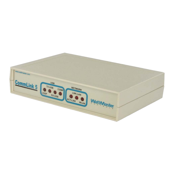
This LED only fl ashes when your CommLink 5 is connected WLAN - Indicates wireless connection to the local area network. to a computer and data is sent to Prism from the CommLink 5 This LED fl ashes on when LAN is transmitting and receiving via USB. -
Page 13: Connecting The Network
Proxy and Firewall Compatibility Only with proper confi guration of the Firewall/Proxy are connections to the CommLink 5 from outside of the local area network going to be possible. Check that the Firewall/Proxy TCP port 39288 is not Proxy and Firewall confi gurations may become necessary set to time out or reset after a specifi... -
Page 14: Troubleshooting
<Ports> NOTE: WattMaster Controls Technical Support cannot trou- • bleshoot internal PC and/or Windows-based operating Verify that CommLink 5 is selected for Type of CommLink system problems. in the Job-Sites Window. • Verify that the correct CommLink mode is selected under Network Confi... -
Page 15: Changing The Usb Serial Com Port Number
The Advanced Settings Window will appear. When the CommLink 5 is fi rst plugged in, it will be assigned a COM port number to be used for communicating with the Prism 2 software. If the port number is 10 or greater, it needs to be changed to a value less than 10 to be recognized by Prism 2. - Page 16 Form: WM-CL5-TGD-01G Printed in the USA October 2014 All Rights Reserved Copyright 2014 WattMaster Controls, Inc. 8500 NW River Park Dr. Parkville, MO 64152 Phone (816) 505-1100 www.wattmaster.com Fax (816) 505-1101...
Need help?
Do you have a question about the CommLink 5 and is the answer not in the manual?
Questions and answers