Table of Contents
Advertisement
Advertisement
Table of Contents

Related Manuals for TRAK-IT Powers TI-C5

Summary of Contents for TRAK-IT Powers TI-C5
- Page 1 TRAK-IT TOOL MODEL TI-C5 OPERATORS MANUAL TI-C5...
- Page 2 INDEX INDEX ÍNDICE ENGLISH Page to 21 FRANÇAIS Page to ** ESPAÑOL Page to ** DEFINITIONS OF SIGNAL WORDS WARNING: Indicates a potentially hazardous situation which, if not avoided, could result in death or serious injury. CAUTION: Indicates a potentially hazardous situation which, if not avoided, may result in mi- nor or moderate injury.
-
Page 3: Safety Instructions
ENGLISH OPERATING and MAINTENANCE MANUAL INDEX 1. SAFETY INSTRUCTIONS..............3 2. SPECIFICATIONS AND TECHNICAL DATA ........10 3. SAFETY DEVICES................11 4. HOW TO USE THE BATTERY AND THE CHARGER ......11 5. HANDLING OF FUEL CELL ..............14 6. INSTRUCTIONS FOR OPERATION..........15 7. MAINTAIN FOR PERFORMANCE ............19 8. - Page 4 Do not incinerate or recycle the empty Fuel Cell. WEAR THE CLOTHINGS AND A PROTECTIVE GEAR SUITABLE FOR THE WORKING ENVIRONMENT Depending on the working environment, wear a long-sleeve work uniform and a protective gear such as a hard hat, safe- ty shoes.
- Page 5 Never use an engine generator or DC power source to charge the Battery. Neglect of this causes a trouble or burnout of the charger. Be sure to charge with Charger Base (Cat.#55618). Be sure to charge the Battery with Charger Base (Cat.#55618).
- Page 6 Gasoline Thinner Do not charge the Battery near any combustible sub- Once the Battery is disconnected from the tool body, be stance. sure to cover it with a pack cap, unless it is used. In order to prevent short-circuiting, cover the terminal block (metal section) of the unused Battery with the pack cap.
- Page 7 11. NEVER USE THE TOOL NEAR THE VOLATILE COM- BUSTIBLE SUBSTANCES Never use the tool near gasoline, thinner, gas, paint or ad- hesive agent, because it could ignite or explode. Check whether or not operating sound is heard, by only connecting the Battery. * The fan inside the tool starts running when battery is on the tool and the contact arm is depressed.
- Page 8 17. WHEN USING THE HOOK, BE SURE TO RELEASE 21. NEVER POINT THE DISCHARGE OUTLET TOWARD YOUR FINGER FROM THE TRIGGER YOURSELF AND OTHER PERSONNEL If the discharge outlet is pointed toward people, serious ac- cidents may be caused when misfiring. Be sure the dis- charge outlet is not pointed toward people when the Fuel Cell and the Battery are inserted or not, loading and unload- ing the fasteners or similar operations.
- Page 9 26. DO NOT DRIVE FASTENERS ON TOP OF OTHER FAS- 36. TAKE GOOD CARE OF THE TOOL TENERS Clean the tool with dry soft cloth. Never use wet cloth or vol- Driving fasteners of the top of other fasteners may cause atile solutions such as thinner, benzine.
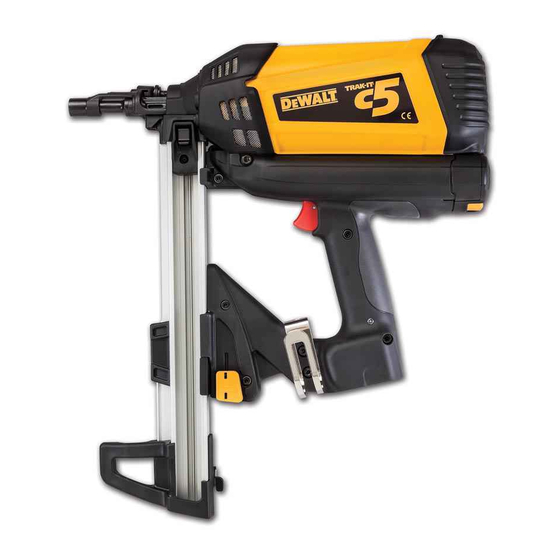
- Page 10 2. SPECIFICATIONS AND TECHNICAL DATA NAME OF PARTS 1 Cylinder Cap Unit b Magazine 2 Fuel Cap c Magazine Foot 3 Housing d Pack Cap 4 LED e Terminal Block 5 Trigger f Battery (Cat.#55583) 6 Battery g Battery Setting Hollow 7 Hook h Jack 8 Nail Stopper...
- Page 11 3. SAFETY DEVICES 4. HOW TO USE THE BATTERY AND THE CHARGER The tool is provided with the following safety devices in order to secure safety for pin driving work. WARNING • Be sure to charge Battery (Cat.#55583) for the tool with Charger Base (Cat.#55618).
- Page 12 HOW TO USE THE CHARGER The special purpose charger Base (Cat.#55618) has the LEDs (green, red) which indicate the status of the charger and Battery. Green LED Red LED Status Description Power-on The charger has been plugged in. (Power-on status:Battery unset) Charging The Battery is being charged.
- Page 13 HOW TO CHARGE WARNING • Charge the Battery at the specified voltage. Be sure to charge from a 100-240 V AC (for household use) plug socket. Use of the non-specified voltage not only causes a trouble, but also is dangerous. •...
- Page 14 Fuel Cap Fuel CAUTION • After completing your work or when the tool is not used, be sure to remove the Battery Pack from the tool to store it. (Remove the Fuel Cell and pins as well) If it is left connected, the electric power will be consumed in the standby state.
- Page 15 DISPOSING OF THE USED FUEL CELL LOADING THE PINS Combustible jet gas still remains in the used Fuel Cell. WARNING WARNING • When loading the pins, be sure to release the finger from • Do not throw the used Fuel Cell into a fire. the Trigger.
- Page 16 HOW TO DRIVE THE PINS DRIVING DEPTH ADJUSTMENT Procedure Install the Battery and Fuel Cell. Press the nose of the Contact Arm against where you want to drive the pins. The fan motor is activated, the fuel gas is jetted, mixing the fuel with the air.
- Page 17 REMOVING THE PIN CHANGING THE HOOK DIRECTION Follower Hexagon Socket Head Cap Screw Hook Follower Holder Pull the Follower Holder and press the Follower, then return the Follow Folder. WARNING Nail Stopper • Remove the Fuel Cell and Battery. The Hook can be directed in the two directions. Remove the hex- agon socket head cap screw with hexagon wrench, change the direction, and then, put back the bolts to reassemble.
- Page 18 REPLACING THE BATTERY Fuel Cell Grab and remove the used Fuel Cell. Set the new Fuel Cell. (See Page 14 for the setting method) If the Battery is low, the red LED of the tool will be turned on. WARNING •...
-
Page 19: Maintain For Performance
INSPECT THE TOOL PERIODICALLY In order to maintain the performance of the tool, clean and inspect the tool periodically. To have it inspected, contact your nearest distributor. Install the newly charged Battery into the Housing until it has clicked. (See Page 13 for the charging method) Install the Fuel Cell. - Page 20 9. TROUBLE SHOOTING/REPAIRS PRODUCTION YEAR INDICATION This product indicates production number at the lower part of the grip. The first 2 digits of the number from left indicates The repairs shall be carried out only by the Powers Fasten- the product year. ers authorized service center.
- Page 21 Magazine Guide (Nose) At this point, the jammed pin should fall out. If the jammed pin does not fall out, carefully remove the pin taking care not to damage the Nosepiece. After you have removed the jammed pin, take the following steps to assemble the Magazine into the tool.
- Page 24 • The content of this manual might be changed without notice for improvement. • Le contenu de ce manuel est sujet a modification sans preavis a des fins d'amelioration. • El contenido de este manual puede ser cambiado sin noticia previa para mejoramiento. •...
Need help?
Do you have a question about the Powers TI-C5 and is the answer not in the manual?
Questions and answers