
Summary of Contents for Severn Trent VAX4600 Series
- Page 1 Instruction Manual — Vaporizer for Chlorine or Sulfur Dioxide Series VAX4600 APITAL ONTROLS - 1 - 115.6001.10...
- Page 2 Severn Trent Water Purification, Inc. cannot be responsible for the overall system design of which our equipment may be an integral part of or any unauthorized modifications to the equipment made by any party other that Severn Trent Water Purification, Inc.
-
Page 3: Table Of Contents
Table of Contents INTRODUCTION ............... . . 5 General . - Page 4 115.6001.10 - 4 -...
-
Page 5: Introduction
115.6020 - Gas Pressure Relief Valve and Rupture Disc Instruction Manual Component Description Series VAX4600 Vaporizer utilizes an electrically heated water bath to add the necessary heat to the liquid chemical for vaporization. The unit consists of a hot water tank, a chemical vaporizing chamber, a NEMA 4X heater control circuit, a NEMA 4X water level control circuit, chemical and hot water monitoring instruments, cathodic protection circuit, and ABS structural foam enclosure. -
Page 6: Vaporizer Flow Diagram
Figure 1 - Vaporizer Flow Diagram Figure 2 - Chemical Boiling Points at System Pressure 115.6001.10 - 6 -... -
Page 7: Chemical Boiling Points At System Pressure
1.2.3 Control Circuits (Refer to Bulletins 115.3024 and 115.3025) a. Heater Control The heater circuit is supplied wired to accommodate one of the following source voltages 240, 480, or 575 Vac, 50/60 Hz, 3 phase (other voltages or single phase are supplied optionally). The heaters are controlled by a tank mounted electrically operated, field- adjustable thermostat which controls the heater magnetic contactor (relay) to regulate water bath temperature. -
Page 8: Specifications
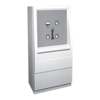
1.2.6 Corrosion Resistant Enclosure (See Figure 4) The enclosure consists of six pieces; a bottom and a top, two sides and a front and back bezel. The bezels are pressure-formed ABS and the sides, top and bottom are structural foam plastic. Easy removal of the front bezel exposes all control and monitoring components. -
Page 9: Cabinet Dimensions & Utility Connection Locations
Figure 4 - Cabinet Dimensions & Utility Connection Locations - 9 - 115.6001.10... -
Page 10: Principle Of Operation
1.3.3 Operating Pressure Vaporizer: Minimum: 45 psi Normal: 100 psi Maximum allowable working pressure: 666 psi @ 212°F (however, rupture disk will rupture at 275 psi) The vaporizer chamber is stamped with a U and W-L stamp which means it is arc or gas welded and for lethal service. -
Page 11: Installation
INSTALLATION Location The vaporizer should be located as close to the liquid chemical source as possible. The length of chemical liquid and gas lines should be kept to a minimum. A vaporizing room should have provisions to exhaust any leaking gas. A lifting device above the vaporizer is also required. See Figure 5 for dimension requirements. Mounting Install the vaporizer on a mounting pad of concrete or other suitable material approximately 2"... -
Page 12: Vaporizer Piping Connections
Figure 6 - Vaporizer Piping Connections 115.6001.10 - 12 -... -
Page 13: Piping
Piping (See Figures 6 and 7 and Bulletins 115.3002 and 115.3003) NOTES: All chemical carrying pipes and fittings must be Schedule 80 seamless steel or forged steel conforming to ASTM A-105 and A-106, Grade B. All piping, valves and fittings must be thoroughly cleaned of all oils and foreign matter prior to assembly in accordance with Chlorine Institute Pamphlet #6. -
Page 14: Wiring
b. Install the pressure reducing valve as shown in Bulletins 115.6010, 115.3002 and Figure 6. NOTE: The pressure reducing valve must be located as close as possible to the gas discharge of the vaporizer. The outlet of the reducing valve should be routed to the process equipment. A 1/4" vent pipe (Schedule 80 seamless steel or forged steel conforming to ASTM A-105 and A-106, Grade B) should terminate outdoors in an area that can tolerate gas discharge. - Page 15 b. Wire the magnetic contactor to a fused safety switch, unless factory installed, and then to the power source. 2.4.2 Control Circuits WARNING: Temperature controls are voltage sensitive. Applying improper voltage will destroy the switch. Wire the control circuit L1 and L2 to a fused safety switch and then to the power source. Wire the electric actuator on the pressure reducing valve or pilot solenoid valve (pneumatic models only) to the vaporizer terminal strip.
-
Page 16: Operation
OPERATION General This section covers the operating practices of the Series VAX4600 Vaporizer System, consisting of one vaporizer, one pressure relief valve, one (optional) pressure reducing valve and one or more liquid line expansion chambers. Pre-startup Components 3.2.1 Vaporizer Apply power to the vaporizer control circuit to energize the automatic water level control and actuate the water fill solenoid valve. -
Page 17: Chlorine And Sulfur Dioxide Vaporizer Components
Figure 8 - Chlorine and Sulfur Dioxide Vaporizer Components - 17 - 115.6001.10... - Page 18 3.3.2 Abnormally High Chemical Supply Pressure CAUTION: Vaporizer performance will be restricted if ton containers and tank cars produce abnormally high liquid pressure. Normal ton container pressure ranges (unpadded) are 85-100 psig (586-690 kPa). Liquid pressure in a padded tank car is normally 125 psig (862 kPa). Vaporizer capacity is reduced by padding and very low liquid chemical temperature.
-
Page 19: Calibration
Calibration 3.4.1 Cathodic Protection Current Adjustment The current level required to prevent electrolytic degradation of the tank and chamber is between 25 and 30 milliamps as read on the instrument panel ammeter. This should be read and adjusted weekly using the potentiometer knob directly below the ammeter. A zero reading at all potentiometer settings indicates replacement of anodes is required. -
Page 20: Service
SERVICE Changing Chemical Supply 4.1.1 With the process equipment operating, shut off the chemical container liquid outlet valve. 4.1.2 Shut off the isolating valve on the flexible connection at the chemical container. 4.1.3 Disconnect the flexible connection from the empty chemical container liquid outlet valve and reconnect to a full chemical container. -
Page 21: Heater Replacement
Install the chamber into the water bath tank in proper orientation and fasten in place with the eight bolts around the top plate. Replace the rubber gasket if required. u. Insert a new lead gasket into the groove in the chamber flange. Install the chamber flange into the chamber. -
Page 22: Water Filling
4.3.7 Connect the two wires to the new element terminals and close the heater enclosure door. 4.3.8 Fill the water bath tank to the proper level by opening the manual filling valve and by energizing the automatic fill solenoid valve. Visually check for water leaks before activating the electrical power to the control circuit. -
Page 23: Low Water Level Alarm And Cutoff Switch
Water Temperature Control Thermostat (Refer to Bulletins 115.3020 and 115.3021) 4.6.1 Check power source and fuse to actuate magnetic contactor coil. 4.6.2 Check power source and fuse to heater circuit. 4.6.3 Check power source and 100 mA sloblow fuse to the temperature control. WARNING: Improper voltage will destroy the switch. -
Page 24: Replacing Heater Element
Figure 10 - Replacing Heater Element 115.6001.10 - 24 -... -
Page 25: Troubleshooting Chart
TROUBLESHOOTING CHART c t i c t i . f f c t i . y r c t i c i t s ’ r . l l i c t i y t l y t l c t i c t i l l i c i t... - Page 26 115.6001.10 - 26 -...
-
Page 27: Certificate Of Conformity
- 27 - 115.6001.10... - Page 28 ONTROLS Severn Trent Services 3000 Advance Lane Colmar, PA 18915 Tel: 215-997-4000 • Fax: 215-997-4062 Web: www.severntrentservices.com E-mail: marketing@severntrentservices.com UNITED KINGDOM • UNITED STATES • HONG KONG ITALY • MALAYSIA 05/06 Copyright 2003 Severn Trent Services 115.6001.10 - 28 -...
Need help?
Do you have a question about the VAX4600 Series and is the answer not in the manual?
Questions and answers