Table of Contents
Advertisement
Quick Links
Advertisement
Table of Contents

Subscribe to Our Youtube Channel
Summary of Contents for Apricus Advanced solar controller
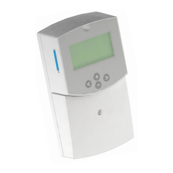
- Page 1 ADVANCED SOLAR CONTROLLER ...
- Page 2 Installation, operation, and maintenance must be performed by qualified personnel, in accordance with applicable codes, standards, and practices. Apricus Solar Co., Ltd. is not responsible for any damages or injuries that result from improper installation, modification, use or applications/configurations other than those detailed in this document. ...
-
Page 3: Table Of Contents
TABLE OF CONTENTS Main and Technical Features ---------------------------------- Page 5 Display ---------------------------------- Page 6 1 Service Menu ---------------------------------- Page 7 1.1 Language 1.2 Time & Date 1.3 System 1.3.1 System 1 ... - Page 4 2.13 Diffcontrol function ---------------------------------- Page 23 2.13.1 Max cold tank (no auxiliary heat source) 2.13.2 Min warm tank (no auxiliary heat source) 2.13.3 Max cold tank (w/auxiliary heat source) 2.13.4 Min warm tank (w/auxiliary heat source) ...
-
Page 5: Main And Technical Features
Features • Large graphic display with backlight • Easy to use interface (4 keys with scroll menu) • Several languages available • System set-up/configuration option using SD card • Record and view system data (Energy, pump operation etc.) with SD card interface ... -
Page 6: Display
DISPLAY (Screen, Keys, Menus) Main Display 1 2 3 T1_ _ _°F T2_ _ _°F T3_ _ _°F Circulation direction T4_ _ _°F 4 T3 P1_ _ _ % _ _ _ BTU/h _ _ _ BTU Activation indicator A NOTE: System 4 shown in example; features typical of all systems. Simplified drawing of the installation. -
Page 7: Service Menu
1 Service Menu 1.1 Language: - With (+) or (-)select the line “English” and press ( >) to highlight the line. - Now you can change the language with (+) or (-), you have the choice between: English, Deutsch, Français, Svenska, Spanish.. ... -
Page 8: System
1.3.2 System 2 System with 2 tanks, 1 pump, 1 valve, 1 collector array and 3 sensors. With this system you can add an extra function with 1 sensor (Thermostat, or Cooling function). T1 _ _ _°F T2 _ _ _°F T4 _ _ _°F P1 _ _ _ % ... -
Page 9: Extra Function
1.4 Extra: When the line is selected, press (>) to highlight the line. You have the choice of 3 extra functions (The choice is not the same with all systems, see the previous section) 1.4.1 Thermostat Function This function may be used to connect an auxiliary or back-up heat source to your system. Some possible auxiliary heat sources: Pump controls for Fuel or Gas burner (P3 provides 120V signal)…... - Page 10 1.4.3 Diffcontrol Function: The Diffcontrol function (only available on System 1) may be used to transfer heated water from one storage tank to another independent of the solar collecting function. This extra function allows separate temperature control of both tanks with user-defined temperature settings (see Settings menu / 2.13).
-
Page 11: External Sensor
1.5 External Sensor: This option is useful for collectors that require the sensor to be mounted on the piping external to the collector manifold. Service--------- - --- -- English Time and date System Extra External sensor Protection func. Flow meter Select External sensor and press (>) to highlight the line. -
Page 12: Cooling
1.6.1 Cooling: Protection func.------------- ----- Collector Max temp 248°F ---- Cooling yes- Recooling Overheat prot. Freeze prot This option is for the protection of the collector fluid. It activates the solar pump (P1 or P2) if the temperature on the collector arrays (T1 or T4) exceeds the collector Max temp value even if the set maximum temperature in the tank is exceeded. -
Page 13: Flow Meter
1.7 Flow meter: The flow meter is used for energy measurement and system monitoring. If no flow meter is installed (factory default setting) you must manually enter the pump flow in gallons/minute using the (+) or (-) buttons. The manufacturer’s specification is generally found in the pump literature or on the manufacturer’s website. -
Page 14: Reset Operation Time
1.9 Reset op time: Service-------- - --- -- Extra External sensor Protection func. Flow meter Gallon / impulse Factory setting Reset op time To reset the all of the operation hours to zero: Press (>) to highlight the line. Select “yes”... -
Page 15: Time Graph Operation
1.13 US Version: This selection allows you to select the units of measurement that will be displayed on the control. Service----------- - ------ Gallon/impulse Factory setting Reset op time Time graph temp Time graph op Calib sensors US version YES = (US Version): °F, 12H am/pm, Gallons, BTU/h and kBTU NO = (EU Version): °C, 24H, Litres, kWh 1.14 Pump P1... -
Page 16: Pump P2
1.15 Pump P2 This function allows you to choose the type of the pump used on the output P2. To change the pump type, press (>) then select your choice with the (+) or (-) buttons. Service----- - ------ Reset op time Time graph temp Time graph op... -
Page 17: Gds2
1.17 GDS2: Service------ - ------ Time graph op Calib sensors US version Pump P1 No SC Pump P2 No SC GDS1 GDS2 NC----- This input is reserved for connection of a Pressure sensor to monitor the primary circuit. Three GF Pressure sensors are supported on the GDS2 port: VPS 0 –... -
Page 18: Setting Menu
2 Setting Menu: This menu allows you to set all adjustable parameters of your system. Not all options are available with all systems. Settings ------------- Maxtemp tank1 149°F dT Max tank1 49°F dT Min tank1 38°F Maxtemp tank2 149°F dT Max tank2 49°F... -
Page 19: Mintemp Prio Tank
2.7 Mintemp prio tank: This will only display on systems configured with two tanks (as discussed in sections 1.3.2 / System 2 and 1.3.3 / System 3) Settings --------------- Maxtemp tank1 149°F dT Max tank1 49°F dT Min tank1 38°F Maxtemp tank2 149°F... -
Page 20: Boost Time (Booster Pump)
2.9 Boost time: Available for System 1 only This option will display only if the Boost setting is chosen for Pump P2 on the Service menu / Pump P2 (See Section 1.15). Settings -------------- dT Max tank1 49°F dT Min tank1 38°F Maxtemp tank2 149°F... -
Page 21: Extra Functions
EXTRA FUNCTIONS The following three options are only available if you have made the corresponding selection on the Service / Extra menu discussed in Section 1.4. 2.11 Thermostat Function: Service--------- - --- English Time and date System Extra thermostat External sensor Protection func. -
Page 22: Cooling Function
2.12 Cooling Function: Service--------- - --- English Time and date System Extra cooling External sensor Protection func. Flow meter 2.12.1 Cooling start: When the water temperature in the top of the system tank (T3) rises above this setting, P3 will activate to start cooling the tank by transferring water to the external tank or heat sink. -
Page 23: Diffcontrol Function
2.13 Diffcontrol Function: Service--------- - --- English Time and date System Extra diffcontrol External sensor Protection func. Flow meter For systems with an additional tank but without an auxiliary heat source (Service/1.4.3 Example 2.13.1 Max cold tank: When the temperature at the top of the external tank (T3) registers above this setting, P3 will shutoff and the exchange of heat will stop (T3 = TC). -
Page 24: Operation Menu
3 Operation M enu : Operation ------------ Automatic (Active) Manual testing 3.1 Automatic and Off operation: To operate your system in Automatic mode, highlight the line and press the (+) or (-) buttons to select Automatic Press (>) to activate. IMPORTANT NOTE: The factory default setting on the Operation Menu is OFF. -
Page 25: Operation Hours Menu
4 Operation h Menu: Operation h------------------ -- --- -- Operation _ _ h _ _°F Power _ _kBTU/h Energy _ _kBTU SD card Deactivated This menu offers both a data view and a graph view for the Operation, dT, Power and Energy values. -
Page 26: Sd Card Option
4.1 SD Card Option You can use the included SD Card to store data and transfer system settings from your PC to the Solar Control. The Dataviewer software that is installed on the SD Card also allows you to view system performance information in graph form. -
Page 27: Using The Dataviewer Software
4.1.3 Using the DataViewer software The DataViewer software is supplied on the USB SD Card Reader. When you insert the Reader/Adapter into a USB port on your computer, you will see a • screen asking what you want Windows to do. Highlight “Open folder to view the files using Windows Explorer”... -
Page 28: Viewing Graphs Of System Data
4.1.5 Viewing Graphs of System Data On the Solar Control: Graphs that you view on the display screen of the Solar Control in the Operation h menu • are based on all system performance measurements. See page 25 for further information. -
Page 29: Temperatures Menu
5 Temperatures Menu: Temperatures---- T1 – Collector1 _ _ _°F T2 – Collector2 _ _ _°F Tank1 bottom _ _ _°F Tank top _ _ _°F This menu displays the temperatures of all connected sensors. Using the (+) or (-) buttons you can select a particular sensor and see its time graph by pressing (>). -
Page 30: Special Functions
6 Special Functions: 6.1 Pump exercise function: If pumps are not activated for a period of 48 hours, this function will automatically activate them for 15 seconds to avoid jams. 6.2 Dimmer function: To save power, the backlight automatically dims if there is no keypad activity for a period of 10 minutes. -
Page 31: Controller Schematic
8 Controller Schematic 31 ... -
Page 32: Limited Warranty
original purchase. During this period, Apricus Solar Co., Ltd. will replace the product or refund the original cost of the product, at Apricus Solar’s option, if the product is proven defective under normal usage within the warranty period. This limited warranty does not cover shipping costs, nor does it cover a product subjected to misuse or accidental damage. This warranty does not cover the cost of installation, diagnosis, ...
Need help?
Do you have a question about the Advanced solar controller and is the answer not in the manual?
Questions and answers