
Related Manuals for Perkins 1206E-E66TA


Summary of Contents for Perkins 1206E-E66TA
- Page 1 SEBU8603-01 May 2011 Operation and Maintenance Manual 1206E-E66TA Industrial Engine BK (Engine)
-
Page 2: Important Safety Information
These changes can affect the service that is given to the product. Obtain the complete and most current information before you start any job. Perkins dealers or Perkins distributors have the most current information available. When replacement parts are required for this product Perkins recommends using Perkins replacement parts. -
Page 3: Table Of Contents
SEBU8603-01 Table of Contents Table of Contents Maintenance Interval Schedule ......78 Warranty Section Foreword ..............4 Warranty Information ........... 110 Safety Section Reference Information Section Safety Messages ............ 5 Reference Materials ..........114 General Hazard Information ........8 Index Section Burn Prevention ............. -
Page 4: Foreword
They assist with developing the skills and Perkins authorized personnel. Your Perkins dealer techniques required to operate the engine more or your Perkins distributor offers a variety of options efficiently and economically. Skill and techniques regarding overhaul programs. If you experience... -
Page 5: Safety Section
Replace any warning sign that is damaged or missing. If a warning sign is attached to a part of the engine that is replaced, install a new warning sign on the replacement part. Your Perkins distributor can provide new warning signs. (1) Universal Warning... - Page 6 SEBU8603-01 Safety Section Safety Messages g02382617 Illustration 2 Typical example (1) Universal warning (2) Hand (High Pressure) Contact with high pressure fuel may cause fluid penetration and burn hazards. High pressure fu- el spray may cause a fire hazard. Failure to fol- low these inspection, maintenance and service in- structions may cause personal injury or death.
-
Page 7: Ether Warning
SEBU8603-01 Safety Section Safety Messages g02382677 Illustration 3 Typical example The warning label for the Hand (High Pressure) (3) is a wrap around label that is installed on the high-pressure fuel line. g02382618 Illustration 4 Typical example Ether Warning Do not use aerosol types of starting aids such as ether. -
Page 8: General Hazard Information
SEBU8603-01 Safety Section General Hazard Information • Vent the engine exhaust to the outside when the engine is operated in an enclosed area. • If the engine is not running, do not release the secondary brake or the parking brake systems unless the vehicle is blocked or unless the vehicle is restrained. -
Page 9: Pressurized Air And Water
SEBU8603-01 Safety Section General Hazard Information • • For initial start-up of a new engine or for starting an Do not wear loose clothing or jewelry that can snag engine that has been serviced, make provisions to on controls or on other parts of the engine. stop the engine if an overspeed occurs. -
Page 10: Containing Fluid Spillage
General Hazard Information Perkins replacement parts that are shipped from Perkins are asbestos free. Perkins recommends the use of only genuine Perkins replacement parts. Use the following guidelines when you handle any replacement parts that contain asbestos or when you handle asbestos debris. -
Page 11: Induction System
SEBU8603-01 Safety Section Burn Prevention Dispose of Waste Properly Allow the pressure to be purged in the air system, in the hydraulic system, in the lubrication system, or in the cooling system before any lines, fittings, or related items are disconnected. Induction System Sulfuric Acid Burn Hazard may cause serious per- sonal injury or death. -
Page 12: Fire Prevention And Explosion Prevention
If the application involves the presence of combustible Ensure that the engine is stopped. Inspect all lines gases, consult your Perkins dealer and/or your and hoses for wear or for deterioration. The hoses Perkins distributor for additional information about must be correctly routed. -
Page 13: Fire Extinguisher
flames or sparks. Always damaged. stop the engine before refueling. Leaks can cause fires. Consult your Perkins dealer or your Perkins distributor for replacement parts. Replace the parts if any of the following conditions are present: •... -
Page 14: Crushing Prevention And Cutting Prevention
SEBU8603-01 Safety Section Crushing Prevention and Cutting Prevention i02143194 Crushing Prevention and Cutting Prevention Support the component correctly when work beneath the component is performed. Unless other maintenance instructions are provided, never attempt adjustments while the engine is running. Stay clear of all rotating parts and of all moving parts. - Page 15 SEBU8603-01 Safety Section High Pressure Fuel Lines g01877473 Illustration 14 (1) High pressure line (4) High pressure line (7) High pressure fuel manifold (rail) (2) High pressure line (5) High pressure line (8) High pressure line (3) High pressure line (6) High pressure line (9) Fuel transfer line that is high pressure The high pressure fuel lines are the fuel lines that...
-
Page 16: Before Starting Engine
These engines are equipped with a glow plug starting engine damage. aid in each individual cylinder that heats the intake air in order to improve starting. Some Perkins engines See the Service Manual for repairs and for may have a cold starting system that is controlled by adjustments. -
Page 17: Electrical System
SEBU8603-01 Safety Section Electrical System Grounding Practices Use the Emergency Stop Button (if equipped) ONLY in an emergency situation. Do not use the Emergency Stop Button for normal engine stopping. After an emergency stop, DO NOT start the engine until the problem that caused the emergency stop has been corrected. -
Page 18: Engine Electronics
SEBU8603-01 Safety Section Engine Electronics The power supply connections and the ground connections for the engine electronics should always be from the isolator to the battery. i03642610 Engine Electronics Tampering with the electronic system installation or the OEM wiring installation can be dangerous and could result in personal injury or death and/or engine damage. - Page 19 Note: Many of the engine control systems and display modules that are available for Perkins Engines will work in unison with the Engine Monitoring System. Together, the two controls will provide the engine monitoring function for the specific engine application.
-
Page 20: Product Information Section
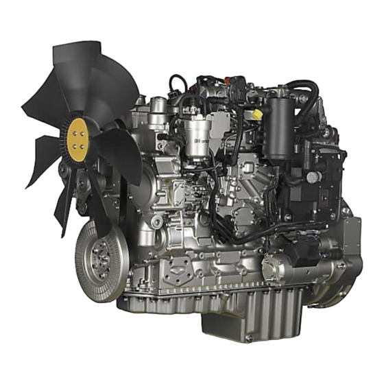
SEBU8603-01 Product Information Section Model Views Product Information Section Model Views i04171351 Model View Illustrations The following model views show typical features of the engine. Due to individual applications, your engine may appear different from the illustrations. Engine views g02361696 Illustration 17 Typical example (1) Secondary fuel filter... - Page 21 SEBU8603-01 Product Information Section Model Views The location of the in-line strainer (5) and the priming pump (7) will depend on the application. g02361697 Illustration 18 Typical example (11) Rear lifting eye (15) Back pressure valve (19) Flywheel housing (12) NOx reduction system (NRS) (16) Engine oil pan (Sump) (20) Flywheel (13) Front lifting eye...
- Page 22 SEBU8603-01 Product Information Section Model Views g02379457 Illustration 19 Typical example (23) Belt (27) Water pump (32) Alternator (24) Connection for air inlet (28) Oil filler (25) Outlet connection for the coolant (29) Inlet connection for the Coolant (26) Water temperature regulator housing (30) Vibration damper (Thermostat housing) (31) Belt tensioner...
- Page 23 SEBU8603-01 Product Information Section Model Views g02381218 Illustration 20 Typical example (33) Coolant drain plug for cylinder block (34) Coolant drain plug for exhaust gas cooler...
-
Page 24: Engine Description
(1) Clean emissions module (CEM) (3) Outlet connection (5) Flexible exhaust pipe from engine to (2) Inlet connection (4) Mounting cradle i04340730 Engine Description The Perkins 1206-E66 Industrial Engine has the following characteristics. • In-line Six cylinder • Four stroke cycle •... -
Page 25: Engine Diagnostics
Operation and Maintenance Manual, “Features and Controls” topic (Operation Section). Aftertreatment System The aftertreatment system is approved for use by Perkins. In order to be emission-compliant only the approved Perkins aftertreatment system must be used on a Perkins engine. -
Page 26: Engine Service Life
Operation and Maintenance Manual, “Overhaul Considerations” topic (Maintenance Section). Aftermarket Products and Perkins Engines Perkins does not warrant the quality or performance of non-Perkins fluids and filters. When auxiliary devices, accessories, or consumables (filters, additives, catalysts,) which are made by other... -
Page 27: Product Identification Information
This information will be required by your depending on the application. Perkins distributor. The information is essential in order to be emissions complaint. i03867276 Reference Numbers Information for the following items may be needed to order parts. -
Page 28: Emissions Certification Film
SEBU8603-01 Product Information Section Product Identification Information Engine Serial number _________ ____________________________ Engine Low Idle rpm _________ _____________________________ Engine Full Load rpm _________ ____________________________ Primary Fuel Filter _________ ________________________________ Water Separator Element _________ _______________________ Secondary Fuel Filter Element _________ _________________ Lubrication Oil Filter Element _________ __________________ Auxiliary Oil Filter Element... -
Page 29: Operation Section
Product Lifting fixtures obsolete. If alterations are made, ensure (Engine) that correct lifting devices are provided. Consult your Perkins dealer or your Perkins distributor for information regarding fixtures for correct engine lifting. g01097527 Illustration 26 NOTICE Never bend the eyebolts and the brackets. -
Page 30: Condition For Storage
The engine must be stored in a water proof building. The building must be kept at a constant temperature. Engines that are filled with Perkins ELC will have coolant protection to an ambient temperature of −36° C (−32.8° F). The engine must not be subjected to extreme variations in temperature and humidity. - Page 31 Operation Section Lifting and Storage 4. Remove the drive belt from the engine. Sealed Coolant System Ensure that the cooling system is filled with Perkins ELC, or an antifreeze that meets “ASTM D6210” specification. Open Cooling System Ensure that all cooling drain plugs have been opened.
-
Page 32: Gauges And Indicators
Determine and correct the cause of any significant If the engine is operating above the normal range, change in the readings. Consult your Perkins reduce the engine load. If high coolant temperatures distributor for assistance. -
Page 33: Indicator Lamps
SEBU8603-01 Operation Section Gauges and Indicators • Oil pressure Service Hour Meter – The gauge indicates • total operating hours of the engine. Intake temperature • Intake pressure Indicator Lamps • Atmospheric pressure There is four indicator lamps that are available. •... -
Page 34: Features And Controls
SEBU8603-01 Operation Section Features and Controls Features and Controls Programmable Options and Systems Operation i04340829 Monitoring System If the Warning/Derate/Shutdown mode has been selected and the warning indicator activates, bring the engine to a stop whenever possible. De- pending on the application, special precautions should be taken to avoid personal injury. - Page 35 Maintenance Manual, “ Monitoring System (Table for Indicator Lamps)”. For each of the programmed modes, refer to Troubleshooting Guide, “Indicator Lamps” for more information on Indicator Lamps. For more information or assistance for repairs, consult your Perkins distributor or your Perkins dealer.
-
Page 36: Monitoring System
SEBU8603-01 Operation Section Features and Controls i04201172 Monitoring System (Table for the Indicator lamps) Note: When in operation the amber warning lamp has three states, solid, flashing, and fast flashing. The sequence is to give a visual indication of the importance of the warning. - Page 37 SEBU8603-01 Operation Section Features and Controls i04215952 Sensors and Electrical Components (Aftertreatment) The illustration within the section shows the typical locations of the sensors and other electrical components on the industrial engine. Specific engine aftertreatment systems may appear different due to the application.
- Page 38 SEBU8603-01 Operation Section Features and Controls g02392837 Illustration 29 Typical example (1) Coolant Temperature Sensor (6) Intake Manifold Pressure Sensor (11) Oil Pressure Sensor (2) Wastegate Regulator (7) Diagnostic Connector (12) Fuel Priming Pump (3) Throttle valve (8) Electronic Control Module (ECM) (13) Water in Fuel Switch (4) Fuel Pressure Sensor (Fuel Rail (9) Atmospheric Pressure Sensor...
- Page 39 SEBU8603-01 Operation Section Features and Controls g02392856 Illustration 30 Typical example (16) Inlet Pressure Sensor for the NOx (18) Control Valve for the NRS (21) Back Pressure Valve Reduction System (NRS) (19) Temperature Sensor for the NRS (22) Secondary Speed/Timing Sensor (17) Outlet Pressure sensor for the NRS (20) Alternator (23) Starter Motor...
- Page 40 SEBU8603-01 Operation Section Features and Controls g02394156 Illustration 31 Typical example (1) Coolant Temperature Sensor (2) Wastegate Regulator (3) Throttle valve g02394157 Illustration 32 Typical example (4) Fuel Pressure Sensor (Fuel Rail (7) Diagnostic Connector (10) Primary Speed/Timing Sensor Pressure Sensor) (8) Electronic Control Module (ECM) (11) Oil Pressure Sensor (5) Intake Manifold Air Temperature Sensor...
- Page 41 SEBU8603-01 Operation Section Features and Controls g02395396 Illustration 33 Typical example (13) Water in Fuel Switch (14) Fuel Temperature Sensor (15) Solenoid for the High Pressure Fuel Pump...
- Page 42 SEBU8603-01 Operation Section Features and Controls g02395399 Illustration 34 Typical example (16) Inlet Pressure Sensor for the NOx (17) Outlet Pressure sensor for the NRS (19) Temperature Sensor for the NRS Reduction System (NRS) (18) Control Valve for the NRS...
- Page 43 SEBU8603-01 Operation Section Features and Controls g02395417 Illustration 35 Typical example (20) Alternator (21) Back Pressure Valve (22) Secondary Speed/Timing Sensor (23) Starter Motor The particular shutoff may need to be reset before i04372685 the engine will start. Engine Shutoffs and Engine Alarms NOTICE Always determine the cause of the engine shutdown.
- Page 44 SEBU8603-01 Operation Section Features and Controls The alarm is operated by a sensor or by a switch. If corrective measures are not taken within a When the sensor or the switch is activated, a signal reasonable time, engine damage could result. The is sent to the ECM.
-
Page 45: Engine Diagnostics
Self-Diagnostics Use the “DIAGNOSTIC” lamp or an electronic service tool to determine the diagnostic flash code. Perkins electronic engines have the capability to perform a self-diagnostics test. When the system Use the following procedure to retrieve the flash detects an active problem, a diagnostic lamp codes if the engine is equipped with a “DIAGNOSTIC”... -
Page 46: Fault Logging
SEBU8603-01 Operation Section Engine Diagnostics (Table 3, contd) (Table 3, contd) Fuel rail pressure sensor out of range 8 V DC Supply voltage out of range Programmed parameter fault erratic, Fuel temperature sensor out of range intermittent, or incorrect 5 Volt Sensor DC Power Supply #2 Engine coolant temperature sensor out of range out of range... -
Page 47: Configuration Parameters
SEBU8603-01 Operation Section Engine Diagnostics i03554534 i01902995 Engine Operation with Active Engine Operation with Intermittent Diagnostic Codes Diagnostic Codes If a diagnostic lamp illuminates during normal engine If a diagnostic lamp illuminates during normal engine operation, the system has identified a situation that operation and the diagnostic lamp shuts off, an is not within the specification. -
Page 48: Customer Specified Parameters
SEBU8603-01 Operation Section Engine Diagnostics Table 4 System Configuration Parameters Configuration Parameters Record Full Load Setting Full Torque Setting Rating Engine Serial Number Factory Installed Aftertreatment Identification Number DPF Soot Loading Sensing System Configuration Code Limp Home Engine Speed Ramp Rate ECM Software Release Date Customer Specified Parameters Customer specified parameters allow the engine to... - Page 49 SEBU8603-01 Operation Section Engine Diagnostics (Table 5, contd) Air Filter Restriction Switch Installation Status Air Filter Restriction Switch Configuration System Operating Voltage Configuration Minimum Ambient Air Temperature Maximum Ambient Air Temperature Shutdown Enable Status Shutdown Delay Time Ambient Temperature Override Enable Status Air Shutoff Intermediate Engine Speed Engine Fan Control...
- Page 50 SEBU8603-01 Operation Section Engine Diagnostics (Table 5, contd) Maximum Air Flow Auxiliary #2 Temperature Minimum Air Flow Auxiliary #2 Temperature Reversing Feature Reverse Operation Early Termination Enable Status Manual Purge Suspend Purge Purge Cycle Interval Purge Cycle Duration Coolant Level Switch Air Filter Restriction Switch Installation Status Air Filter Restriction Switch Configuration Water in Fuel Switch Installation Status...
-
Page 51: Engine Starting
SEBU8603-01 Operation Section Engine Starting Engine Starting i04084389 Starting the Engine i03648917 Before Starting Engine Note: Do not adjust the engine speed control during start-up. The electronic control module (ECM) will control the engine speed during start-up. Perform the required daily maintenance and other periodic maintenance before the engine is started. -
Page 52: Starting With Jump Start Cables
SEBU8603-01 Operation Section Engine Starting Startability will be improved at temperatures below 7. Operate the engine at low load until all systems −18 °C (0 °F) from the use of a jacket water heater reach operating temperature. Check the gauges or extra battery capacity. -
Page 53: After Starting Engine
SEBU8603-01 Operation Section Engine Starting 3. Connect one negative end of the jump start cable i02330138 to the negative cable terminal of the electrical After Starting Engine source. Connect the other negative end of the jump start cable to the engine block or to the chassis ground. -
Page 54: Engine Operation
SEBU8603-01 Operation Section Engine Operation Engine Operation Engine Operation and a DPF During normal engine operation, the operator of the engine may notice the lack of black smoke from the i03858430 exhaust system. Engine Operation Passive regeneration is the process that is used by the DPF in order to remove soot from the DPF. -
Page 55: Fuel Conservation Practices
Fuel Conservation Practices The efficiency of the engine can affect the fuel economy. Perkins design and technology in manufacturing provides maximum fuel efficiency in all applications. Follow the recommended procedures in order to attain optimum performance for the life of the engine. -
Page 56: Engine Stopping
SEBU8603-01 Operation Section Engine Stopping Engine Stopping i03648931 After Stopping Engine i02334873 Stopping the Engine Note: Before you check the engine oil, do not operate the engine for at least 10 minutes in order to allow the engine oil to return to the oil pan. NOTICE Stopping the engine immediately after it has been working under load, can result in overheating and ac-... - Page 57 SEBU8603-01 Operation Section Engine Stopping • Check the coolant for correct antifreeze protection and the correct corrosion protection. Add the correct coolant/water mixture, if necessary. • Perform all required periodic maintenance on all driven equipment. This maintenance is outlined in the instructions from the OEM.
-
Page 58: Cold Weather Operation
“Starting with Jump Start Cables.” for instructions. Recommendations from your Perkins dealer or Viscosity of the Engine Lubrication your Perkins distributor are based on past proven practices. The information that is contained in this section provides guidelines for cold-weather operation. -
Page 59: Idling The Engine
240 V dc. The output can be 750/1000W. Consult temperature is 80° C (176° F) minimum. Carbon your Perkins dealer or your Perkins distributor for deposits on the valve stems will be kept at a minimum more information. - Page 60 Operation Section Cold Weather Operation Note: Do not restrict the air flow. Restriction of i02685960 the air flow can damage the fuel system. Perkins Fuel and the Effect from Cold discourages the use of all air flow restriction Weather devices such as radiator shutters. Restriction of the air flow can result in the following: high exhaust...
-
Page 61: Fuel Filters
SEBU8603-01 Operation Section Cold Weather Operation i02323237 Fuel Related Components in Cold Weather Fuel Tanks Condensation can form in partially filled fuel tanks. Top off the fuel tanks after you operate the engine. Fuel tanks should contain some provision for draining water and sediment from the bottom of the tanks. -
Page 62: Maintenance Section
SEBU8603-01 Maintenance Section Refill Capacities Maintenance Section i04229329 Fluid Recommendations Refill Capacities General Coolant Information i03995972 Refill Capacities NOTICE Never add coolant to an overheated engine. Engine damage could result. Allow the engine to cool first. Lubrication System NOTICE If the engine is to be stored in, or shipped to an area The refill capacities for the engine crankcase with below freezing temperatures, the cooling system reflect the approximate capacity of the crankcase... -
Page 63: Coolant Recommendations
Table 8 • Acceptable Water Cavitation of the water pump Property Maximum Limit For optimum performance, Perkins recommends a 1:1 mixture of a water/glycol solution. Chloride (Cl) 40 mg/L Sulfate (SO 100 mg/L Note: Use a mixture that will provide protection... -
Page 64: Elc Cooling System Maintenance
Heavy-duty diesel engines _________ _________________________________ Society for Testing and Materials • Automotive applications The following two coolants are used in Perkins diesel engines: The anti-corrosion package for ELC is different from the anti-corrosion package for other coolants. ELC Preferred – Perkins ELC is an ethylene glycol base coolant. -
Page 65: Elc Cooling System Cleaning
8. Repeat Steps 6 and repeat steps 7 until the system is completely clean. Changing to Perkins ELC 9. Fill the cooling system with the Perkins Premixed To change from heavy-duty antifreeze to the Perkins ELC. ELC, perform the following steps:... - Page 66 Check the antifreeze (glycol concentration) in order to ensure adequate protection against boiling Table 14 or freezing. Perkins recommends the use of a refractometer for checking the glycol concentration. Equation For Adding The SCA To The Heavy-Duty Coolant For Maintenance A hydrometer should not be used.
-
Page 67: Engine Oil
“EMA Recommended Guideline on Diesel Engine interval that is optimum. Oil”. In addition to Perkins definitions, there are other definitions that will be of assistance in purchasing Note: These engine oils are not approved by lubricants. -
Page 68: Aftermarket Oil Additives
finished oil. This failure could produce sludge temperature during engine operation. in the crankcase. Perkins discourages the use of aftermarket additives in finished oils. Refer to illustration 37 (minimum temperature) in... -
Page 69: General Information
17. • Glossary NOTICE • ISO International Standards Organization The footnotes are of the key part Perkins Specifica- tion for Distillate Diesel Fuel Table. Read ALL of the • ASTM American Society for Testing and Materials footnotes. •... - Page 70 SEBU8603-01 Maintenance Section Refill Capacities Table 17 Perkins Specification for Distillate Diesel Fuel Property UNITS Requirements “ASTM”Test “ISO”Test Aromatics %Volume 35% maximum D1319 “ISO”3837 %Weight 0.01% maximum D482 “ISO”6245 Carbon Residue on %Weight 0.35% maximum D524 “ISO”4262 10% Bottoms Cetane Number...
- Page 71 Note: The owner and the operator of the engine has the responsibility of using the fuel that is prescribed by the EPA and other appropriate regulatory agencies. NOTICE Operating with fuels that do not meet the Perkins rec- ommendations can cause the following effects: Start- g02157153 Illustration 38 ing difficulty, reduced fuel filter service life, poor com-...
-
Page 72: Diesel Fuel Characteristics
“EU Off Road Diesel fuel. Acceptable from 2011 MUST have less than 10 PPM sulfur level” All the fuels must comply with the specification in the table for the Perkins Specification Distillate Diesel Fuel. Diesel Fuel Characteristics The viscosity of the fuel is significant because fuel serves as a lubricant for the fuel system components. - Page 73 Your fuel supplier Protection Agency (EPA) and European Certification can make recommendations for additives to use, and fuels. Perkins does not certify engines on any other for the proper level of treatment. fuel. The user of the engine has the responsibility...
- Page 74 Perkins strongly recommended that seasonally • Perkins recommend the use of oil analysis in order operated engines have the fuel systems, including to check the quality of the engine oil if biodiesel fuel tanks, flashed with conventional diesel fuel fuel is used.
- Page 75 80 hours. Perkins fuel cleaner can be used on an be used for fuel tanks and fuel lines. on-going basis with no adverse impact on engine or fuel system durability.
-
Page 76: Maintenance Recommendations
Allow the cooling system pressure cap onto a chassis frame or rail. Consult the OEM of the to cool. Remove the cooling system pressure cap equipment or your Perkins dealer regarding welding slowly in order to relieve pressure. on a chassis frame or rail. - Page 77 SEBU8603-01 Maintenance Section Maintenance Recommendations 2. Ensure that the fuel supply to the engine is turned off. 3. Disconnect the negative battery cable from the battery. If a battery disconnect switch is provided, open the switch. 4. Disconnect all electronic components from the wiring harnesses.
-
Page 78: Maintenance Interval Schedule
SEBU8603-01 Maintenance Section Maintenance Interval Schedule Every 1500 Service Hours i04220877 Maintenance Interval Schedule Engine Crankcase Breather Element - Replace ... 92 Every 2000 Service Hours Aftercooler Core - Inspect ........79 When Required Engine Mounts - Inspect ........95 Battery - Replace .......... -
Page 79: Battery - Replace
Aftercooler Core - Clean/Test Alternator - Inspect (Air-To-Air Aftercooler) Perkins recommends a scheduled inspection of the alternator. Inspect the alternator for loose The air-to-air aftercooler is OEM installed in many connections and correct battery charging. Check the applications. Please refer to the OEM specifications ammeter (if equipped) during engine operation in for information that is related to the aftercooler. -
Page 80: Battery Or Battery Cable - Disconnect
SEBU8603-01 Maintenance Section Battery Electrolyte Level - Check The battery cables or the batteries should not be All lead-acid batteries contain sulfuric acid which removed with the battery cover in place. The bat- can burn the skin and clothing. Always wear a face tery cover should be removed before any servic- shield and protective clothing when working on or ing is attempted. -
Page 81: Every 500 Service Hours Belt - Inspect
SEBU8603-01 Maintenance Section Belt - Inspect • 3. Remove the positive connection. Inspect the belt for cracks, splits, glazing, grease, displacement of the cord and evidence of fluid 4. Clean all disconnected connection and battery contamination. terminals. The belt must be replaced if the following conditions 5. -
Page 82: Every 3000 Service Hours Or 2 Years Cooling System Coolant (Commercial Heavy-Duty) - Change
The full distillation with the engine on level ground. This will allow you to procedure is the only method acceptable by Perkins to accurately check the coolant level. This will also help reclaim the coolant. -
Page 83: Every 12 000 Service Hours Or 6 Years Cooling System Coolant (Elc) - Change
SEBU8603-01 Maintenance Section Cooling System Coolant (ELC) - Change Flush 4. Maintain the coolant level at the maximum mark that is correct for your application. 1. Flush the cooling system with clean water in order to remove any debris. 2. Close the drain cock or install the drain plug in the engine. - Page 84 The full distillation components are cool. Loosen the cooling system procedure is the only method acceptable by Perkins to pressure cap slowly in order to relieve the pres- reclaim the coolant.
-
Page 85: Cooling System Coolant Level - Check
(1.3 US gal) per minute, in order to avoid air locks. Note: The cooling system may not have been provided by Perkins. The procedure that follows is for typical cooling systems. Refer to the OEM Cooling system air locks may result in engine damage. -
Page 86: Cooling System Supplemental Coolant Additive (Sca) - Test/Add
SEBU8603-01 Maintenance Section Cooling System Supplemental Coolant Additive (SCA) - Test/Add 3. Pour the correct coolant mixture into the tank. Refer to the Operation and Maintenance Manual, “Refill Capacities and Recommendations” for Pressurized System: Hot coolant can cause seri- information on the correct mixture and type of ous burns. -
Page 87: Cooling System Water Temperature Regulator - Replace
SEBU8603-01 Maintenance Section Cooling System Water Temperature Regulator - Replace Add the SCA, If Necessary 4. Clean the cooling system filler cap and inspect the gasket. If the gasket is damaged, discard the old filler cap and install a new filler cap. If the gasket NOTICE is not damaged, use a suitable pressurizing pump Do not exceed the recommended amount of sup-... -
Page 88: Engine - Clean
Failure to replace your water temperature regulator on a regularly scheduled basis could cause severe engine damage. Perkins engines incorporate a shunt design cooling system and require operating the engine with a water temperature regulator installed. Personal injury or death can result from high volt- age. -
Page 89: Engine Air Cleaner Element (Dual Element) - Clean/Replace
Servicing the Air Cleaner Elements Note: The air filter system may not have been provided by Perkins. The procedure that follows is for a typical air filter system. Refer to the OEM information for the correct procedure. - Page 90 SEBU8603-01 Maintenance Section Engine Air Cleaner Element (Dual Element) - Clean/Replace Cleaning the Primary Air Cleaner Pressurized Air Elements Refer to the OEM information in order to determine Personal injury can result from air pressure. the number of times that the primary filter element can be cleaned.
-
Page 91: Engine Air Cleaner Element (Single Element)
SEBU8603-01 Maintenance Section Engine Air Cleaner Element (Single Element) - Inspect/Replace Note: Refer to “Inspecting the Primary Air Cleaner Elements”. NOTICE Never service the air cleaner element with the engine Inspecting the Primary Air Cleaner running since this will allow dirt to enter the engine. Elements A wide variety of air cleaners may be installed for use with this engine. -
Page 92: Engine Air Precleaner - Check/Clean
(1). For information on aftermarket products, refer Note: When the engine is operated in dusty to Operation and Maintenance Manual, “Engine applications, more frequent cleaning is required. Description”. Within that section, refer to the title “Aftermarket Products and Perkins Engines”. -
Page 93: Top Service
SEBU8603-01 Maintenance Section Engine Crankcase Breather Element - Replace The breather element can be serviced from the top position or the breather element can be serviced from the bottom position. Top Service g02346497 Illustration 54 Typical example (B) Alignment position 4. -
Page 94: Bottom Service
SEBU8603-01 Maintenance Section Engine Crankcase Breather Element - Replace 7. Remove the container. Bottom Service Ensure that dirt cannot enter the breather assembly. g02346498 Illustration 56 g02346499 Illustration 57 (X) Alignment mark (Y) Alignment mark Typical example (A) Alignment postion 1. -
Page 95: Check The System
Note: The engine mounts may not have been supplied by Perkins. Refer to the OEM information Note: After the engine has been switched OFF, wait for further information on the engine mounts and the for 10 minutes in order to allow the engine oil to drain correct bolt torque. -
Page 96: Engine Oil Sample - Obtain
Hot oil and hot components can cause personal Perkins recommends using a sampling valve in order injury. Do not allow hot oil or hot components to to obtain oil samples. The quality and the consistency contact the skin. -
Page 97: Fill The Oil Pan
Perkins oil filters are manufactured to Perkins speci- fications. Use of an oil filter that is not recommended by Perkins could result in severe damage to the en- gine bearings, crankshaft, etc., as a result of the larger waste particles from unfiltered oil entering the engine lubricating system. -
Page 98: Fuel System - Prime
SEBU8603-01 Maintenance Section Fuel System - Prime Note: Operating the engine for this period will help i03906114 ensure that the fuel system is free of air. DO NOT Fuel System - Prime loosen the high-pressure fuel lines in order to purge air from the fuel system. - Page 99 SEBU8603-01 Maintenance Section Fuel System Primary Filter (Water Separator) Element - Replace 2. Place a suitable container under the water separator in order to catch any fuel that might spill. Clean up any spilled fuel. Clean the outside body of the filter assembly. 3.
-
Page 100: Fuel System Primary Filter/Water Separator - Drain
System Filter - Replace”. In-line Strainer The fuel system has an in-line strainer installed before g02148370 the electric priming pump. Perkins recommended Illustration 65 that the in-line strainer be replaced when required. Typical example The location of the in-line strainer will depend on the... -
Page 101: Fuel System Secondary Filter - Replace
SEBU8603-01 Maintenance Section Fuel System Secondary Filter - Replace 3. Install a suitable tube onto drain (3). Open the drain valve (2). Rotate the drain valve counterclockwise. Two full turns are required. Loosen vent screw (1). Note: Two complete rotations of the valve will release the valve from the filter element. -
Page 102: Every 50 Service Hours Or Weekly Fuel Tank Water And Sediment - Drain
SEBU8603-01 Maintenance Section Fuel Tank Water and Sediment - Drain 3. Do not use a tool in order to install the filter assembly. Tighten the assembly by hand. Install the filter bowl (2) and align with your temporary Marks. 4. Tighten the drain valve (3). Turn the fuel supply valve to the ON position. -
Page 103: Hoses And Clamps - Inspect/Replace
SEBU8603-01 Maintenance Section Hoses and Clamps - Inspect/Replace Open the drain valve on the bottom of the fuel tank If you inspect the engine in operation, always use in order to drain the water and the sediment. Close the proper inspection procedure in order to avoid the drain valve. -
Page 104: Radiator - Clean
Repeat the cleaning, if necessary. Inspect the fins for damage. Bent fins may be opened The radiator is not usually supplied by Perkins. The with a “comb”. Inspect these items for good condition: following text describes a typical cleaning procedure Welds, mounting brackets, air lines, connections, for the radiator. -
Page 105: Severe Service Application - Check
Frequent hot shutdowns Refer to the standards for the engine or consult your • Operating at excessive loads Perkins dealer or your Perkins distributor in order to determine if the engine is operating within the defined • Operating at excessive speeds parameters. -
Page 106: Turbocharger - Inspect
Refer to the Systems Operation, Testing and Adjusting Manual, “Electric Starting System - Test” for more information on the checking procedure and for specifications or consult your Perkins dealer or your Perkins distributor for assistance. i04287011 Turbocharger - Inspect Hot engine components can cause injury from burns. -
Page 107: Walk-Around Inspection
Refer to Disassembly and Assembly , “Water Pump - Typical example Remove and Install”. For more information, consult your Perkins dealer or your Perkins distributor. Inspect the breather tube (1) for damage. Ensure that the outlet (2) is clean and free from any obstructions. -
Page 108: Water Pump - Inspect
SEBU8603-01 Maintenance Section Water Pump - Inspect High Pressure Fuel Lines i03570653 Water Pump - Inspect Contact with high pressure fuel may cause fluid penetration and burn hazards. High pressure fu- A failed water pump may cause severe engine el spray may cause a fire hazard. Failure to fol- overheating problems that could result in the following low these inspection, maintenance and service in- conditions:... - Page 109 SEBU8603-01 Maintenance Section Water Pump - Inspect The water pump is not a serviceable item. In order to install a new water pump, refer to the Disassembly and Assembly Manual, “Water Pump - Remove and Install”.
-
Page 110: Warranty Section
Federal Emission Control Warranty As a condition of reimbursement, replaced parts and receipted invoices must be presented at a place of business of a Perkins distributor or your Perkins dealer. Or other establishment authorized by Perkins Engine Company limited Emissions Warranty... - Page 111 • The costs in order to investigate complaints which Maintenance Recommendations are not caused by a defect in Perkins Engine Company limited material or Perkins Engine Perkins Engines Company Limited engines are Company limited workmanship. certified by the EPA and the CARB in order to comply with exhaust emission standards and gaseous •...
-
Page 112: Warranty Statement
Perkins Engines Company Limited warrants to the be tested by an authorized Perkins distributor/dealer . initial owner and to the subsequent owner of the 1206E-E66TA diesel engine that such an engine is: TURBOCHARGER – Refer to this Operation and Maintenance Manual, “Turbocharger - Inspect” for 1. - Page 113 • labor rate. The costs in order to investigate complaints which are not caused by a defect in Perkins Engines As a condition of reimbursement, replaced parts Company Limited material or Perkins Engines and receipted invoices must be presented at a Company Limited workmanship.
-
Page 114: Reference Information Section
To purchase an Extended Service Contract, is quick and simple! Contact your local Perkins Distributor Section now and the distributor can provide you with a quote in minutes. You can locate your nearest Perkins Distributor by visiting: Reference Materials www.perkins.com... -
Page 115: Index
Recommendations for Coolant Warm Up ..59 Engine Description ..........24 Recommendations for the Coolant ....58 Aftermarket Products and Perkins Engines ..26 Viscosity of the Engine Lubrication Oil....58 Aftertreatment System ........25 Cold Weather Starting ........... 51 Electronic Engine Features........ - Page 116 SEBU8603-01 Index Section General Hazard Information ........8 Engine Shutoffs and Engine Alarms...... 43 Alarms..............43 Asbestos Information ......... 10 Shutoffs.............. 43 Containing Fluid Spillage ........10 Testing..............44 Dispose of Waste Properly ......... 11 Engine Starting ..........16, 51 Fluid Penetration..........
- Page 117 SEBU8603-01 Index Section Radiator - Clean ..........104 Reference Information Section ......114 Reference Materials ..........114 Reference Numbers ..........27 Record for Reference......... 27 Refill Capacities............. 62 Cooling System..........62 Lubrication System ..........62 Safety Messages ............. 5 (1) Universal Warning .......... 5 (2) Hand (High Pressure)........
- Page 118 SEBU8603-01 Index Section...
- Page 119 Product and Dealer Information Note: For product identification plate locations, see the section “Product Identification Information” in the Operation and Maintenance Manual. Delivery Date: Product Information Model: Product Identification Number: Engine Serial Number: Transmission Serial Number: Generator Serial Number: Attachment Serial Numbers: Attachment Information: Customer Equipment Number: Dealer Equipment Number:...
- Page 120 ©2011 Perkins Engines Company Limited Printed in U.K. All Rights Reserved...
Need help?
Do you have a question about the 1206E-E66TA and is the answer not in the manual?
Questions and answers