Table of Contents
Advertisement
Quick Links
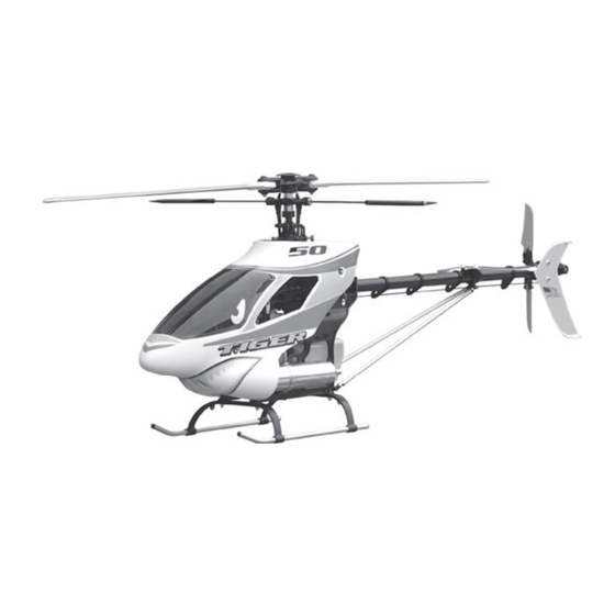
Tiger 50 Remote Control Model Helicopter - Assembly and Maintenance Manual
Audacity Models . . . where performance exceeds expectations!
For technical updates, and
additional information visit:
www.audacitymodels.com
Entire Contents © Copyright 2004
PLEASE READ THIS MANUAL FULLY AND CAREFULLY!
This helicopter model is not a toy and is not suited for children.
Contact with the rotating parts of this model helicopter may
cause bodily harm and/or death as well as property damage.
You, and you alone, are responsible for the safe operation of
this remote controlled model helicopter. Audacity Models
assumes no liability for harm or damage that could occur from
the assembly and/or use/misuse of this product. This manual
does not serve as a final and total instruction in the safe and
proper assembly and operation of remote controlled models.
CCPM
.
Cyclic
.
Collective
.
Pitch
.
Mixing
Advertisement
Table of Contents

Summary of Contents for Audacity Models Tiger 50
-
Page 1: Preparation For Assembly
Tiger 50 Remote Control Model Helicopter - Assembly and Maintenance Manual Audacity Models . . . where performance exceeds expectations! For technical updates, and additional information visit: www.audacitymodels.com CCPM Cyclic Collective Pitch Mixing Entire Contents © Copyright 2004 PLEASE READ THIS MANUAL FULLY AND CAREFULLY! This helicopter model is not a toy and is not suited for children. -
Page 2: Table Of Contents
You, and you alone, are responsible for the safe operation of this R/C model helicopter and Audacity Models assumes no liability for harm or damage that could occur from the assembly and/or use/misuse of this product. This manual does not serve as a final and total instruction in the safe and proper assembly and operation of remote controlled model helicopters. - Page 3 ITEMS NEED TO COMPLETE 6-channel - or greater R/C Helicopter System w/120 CCPM capabilities Gyroscope Drive Washer Not Included with model helicopter Glo-Fuel Pump 50-class Glo-Fuel Engine Helicopter Fuel (15%-30% Nitro) 12V Gell-Cell Battery 6mm Hex Start Shaft 1.2V Ni-Start Battery and Electric Starter Servo Extensions Fuel Filter...
- Page 4 TOOLS NEEDED FOR ASSEMBLY Nut Drivers (4mm/5.5mm/7mm) Phillips Screw Driver Allen Drivers (1.5mm/2mm/2.5mm/3mm) Drill Bit 1/16” Small Hammer Auger - or - Reamer Wrench (5.5mm/6mm) Lexan Scissors Needle-nose Pliers Hobby Knife 4-way Wrench (8-12mm) Ruler (metric) Greater Than 30cm Pitch Gauge Thread Locker Is Used To Keep Assemblies Tight As Vibration May Cause Them To Loosen Due to the vibrations caused by operation, nuts, bolts, and set screws may have a tendency to loosen.
- Page 5 HARDWARE IDENTIFICATION Various size nuts, bolts, set screws, and washers are used in the Tiger 50 helicopter. Metric dimensions are given, first specifying the diameter of the bolt or screw, then the length of the bolt or screw. Washers and nuts are identified by the ID (inner diameter) of the piece.
-
Page 6: Clutch Bell
1.1 CLUTCH BELL * NOTE: Thoroughly clean the shaft-threads and the hole-threads of any swarf (tiny metal shavings), before applying thread locker to ensure precise alignment * NOTE: Use a rocking between the pinion gear and clutch bell. Use special care to prevent thread locker from entering the bearing! side-to-side motion to slip bearing onto shaft. -
Page 7: Elevator Link
1.3 ELEVATOR LINK * NOTE: Mold marks * VERIFY: swashplate must face aft - toward 14.5mm Long Ball Arm (x1) arm pivots freely on the swashplate ball. the elevator arm. Elevator Arm Pin (x1) M2x10mm Socket Fore Head Bolt (x2) M2mm Flat Washer (x2) Elevator Arm Swashplate Arm Link... -
Page 8: Servo-Boss
2.1 SERVO-BOSS * NOTE: Do not glue the servo boss * NOTE: Notches plates into place! must face toward each other! Servo Mount Boss Main Frame - Right Main Frame - Left... -
Page 9: Main Frame
2.2 MAIN FRAME M3x8mm Socket Head Bolt (x2) * PRO TIP: add a small dab of silicone RTV at the four fuel tank M3x38mm Socket Head Bolt (x16) mounting points when you assemble the fuel tank assembly into the main frame assembly. M3x12mm Socket Head Bolt (x1) M3mm Nylon Lock Nut (x16) Elevator Arm Bushing 32mm (x1) -
Page 10: Avionics Platforms
2.3 AVIONICS PLATFORMS M3x10mm Socket head Bolt (x8) Cabin Mount Stand-off 20mm (x2) Cabin Mount Stand-off 10mm (x2) Cabin Mount Stand-off 20mm (x2) M3x14 Set Screw (x2) Gyroscope Platform M3x12 Set Screw (x2) M3x14 Set Screw (x2) M3x10mm Socket head Bolt (x8) * NOTE: Don’t use thread locker on plastic parts! -
Page 11: Landing Gear
3.1 LANDING GEAR M3x15mm Socket Head Bolt (x4) M3x6mm Set Screw (x4) M3x15mm Socket Head Bolt (x4) M3mm Nylon Lock Nut (x4) M3mm Flat Washer (x8) * PRO TIP: Use nylon zip-ties instead of socket head bolts and nylon lock nuts to secure landing gear struts to the main frame - this helps prevent greater damage in case you... -
Page 12: Main Gear & Shaft
MAIN GEAR & SHAFT M4x4mm Set Screw (x3) Mast Stopper M4x4mm Set Screw (x3) M3x22 Socket Head Shoulder Bolt (x1) Gently draw up the NOTE main mast to remove the slack. M3mm Nylon Lock Nut (x1) Long Evenly tighten the M4x4 set screws in the mast stopper (use thread locker). -
Page 13: Engine Mount & Fan
3.3 ENGINE MOUNT & FAN M3x15mm Socket * PRO TIP: Using a marker, place a dot on the Head Bolts (x4) clutch hub - then use a dial indicator to check for excessive runout. Time spend here may pay off in a smoother running helicopter. M3x8mm Socket Simply loosening and rotating the assembly Head Bolts (x4) -
Page 14: Engine & Start Shaft
3.5 ENGINE & START SHAFT VERIFY M3x12mm Socket Head Bolt (x4) There is a slight amount of adjustment for the engine mount to fit within the main M3mm Cap Bolt Holder (x4) frames. This adjustment is for the purpose Angled - INCORRECT of aligning the clutch. -
Page 15: Swashplate/Washout
4.1 SWASHPLATE/WASHOUT Washout Assembly * PRO TIP: Lubricate the washout slider with a few drops of light machine oil such as 3-in-1 daily. Guide Pin Swashplate Assembly VERIFY Hollow Main Shaft (lighter & stronger The washout links must than solid shaft) connect to the two longer-stud balls on the swashplate inner ring. -
Page 16: Head & Flybar Arm
4.2 HEAD & FLYBAR ARM M3x20mm Socket Head Shoulder Bolt (x1) M3mm Nylon Lock Nut (x1) Rotor Head Assembly M2x10mm Phillips Head Screw (x2) Fly Bar * PRO TIP: This Stopper shoulder bolt is M3x5mm Set Screw (x2) also known as a Jesus bolt. -
Page 17: Flybar Paddles
4.4 FLYBAR PADDLES Flybar Paddle M3mm Nylon Locking Nut (x2) * NOTE: Both flybar paddles plus the flybar control arm should (all three) be M4x6mm Set Screw (2) perfectly parallel to each other. 3x70mm weight (x2) 3x70mm weight (x2) M4x6mm Set Screw (2) * NOTE: Flybar paddles - short leading * PRO TIP: For greater agility, edge section forward - clockwise rotation. -
Page 18: Tail Gear Box & Belt
5.1 TAIL GEAR BOX & BELT Tail Drive Belt S3M-1596 Bearing L-1350ZZ M5x13x4mm (x2) Short Slot Tail Boom (L=690mm) Long Tail Output Shaft Bearing Slot L-1350ZZ (x2) 5x13x4mm Tail Gear Case (L) Tail Gear Case (R) 5.2 TAIL OUTPUT SHAFT M2.6x12mm Socket Head Bolt (x2) * NOTE: Ensure the bearing is in place, then slip the tail... -
Page 19: Tail Pitch Lever
5.3 TAIL PITCH LEVER Tail Pitch Link Tail Pitch Plate M2x8mm Phillips Head Screw (x1) Tail Pitch Link Pin Stainless Steel Ball (x1) Tail Lever Bushing (x1) VERIFY Pins Tail Lever Tail Pitch Bushing (x1) Control Lever Stainless Steel Ball (x1) * NOTE: Ensure tail pitch control lever M2x8mm Phillips Head Screw (x1) pins fully engage the slot in the tail... -
Page 20: Tail Rotor Grip
5.5 TAIL ROTOR GRIP M2x8mm Phillips Head Screw (x2) M2x8mm Socket Head Bolt (x4) M2x8mm Phillips Head Screw (x2) M3x15mm Socket Head Bolt (x2) Stainless Steel Ball (x2) M2mm Hex Nut (x4) M2x8mm Socket Head Bolt (x4) M3mm Nylon Lock Nut (x2) Stainless Steel Ball (x2) M3x15mm Socket Head Bolt (x2) * PRO TIP: Snug the tail rotor blade bolts,... -
Page 21: Tail Boom Assembly
5.7 TAIL BOOM ASSEMBLY * NOTE: Ensure the orientation and the tension of the tail drive belt are correct. Verify the tail M3x38mm Socket Head Bolt (x4) rotor output shaft is perpendicular to the main shaft by sighting from behind. Then set the tension in the belt as noted below and tighten both the bolts in the main frame plus the set M3mm Nylon Lock Nut (x4) -
Page 22: Tail Boom Supports
5.8 TAIL BOOM SUPPORTS M2.6x10mm Socket Head Bolt (x4) M2.6mm Nylon Lock Nut (x4) Tail Boom Support (x2) M2.6mm Nylon Lock Nut (x4) M2.6x10mm Socket Head Bolt (x4) Tail Boom Support End (x4) 5.9 BOOM SUPPORT CLAMP M3x10mm Socket Head Bolt (x2) M3x12mm Socket Head Bolt (x2) M3x12mm Socket Head Bolt (x2) M3mm Nylon... -
Page 23: Servo Installation
Swash Right Servo to be tremendously strong. The Tiger 50 has been extensively flown with standard 40-oz ball bearing servos - with excellent results. However, extreme performance pilots will notice a nice improvement when upgrading to digital servos. -
Page 24: Tail Rotor Pushrod
6.2 TAIL ROTOR PUSHROD * NOTE: Slip pushrod bushings onto pushrod before the second ball link. LONG - HD Ball Link Ends (x2) T/R Pushrod Bushings (x4) T/R (tailrotor) Pushrod LONG - HD Ball Link Ends (x2) T/R pushrod = 675mm between the link ends 675mm Length when servo arm and tail rotor control arm... -
Page 25: Avionics Isolation
6.4 AVIONICS ISOLATION CAUTION The importance of protecting the avionics package (receiver, gyro amplifier, governor, and battery pack) from the primary vibrations caused by the engine and the secondary vibrations induced by the main and tail rotors cannot be overemphasized. These forces may lead to premature failure of the avionics components leading to intermittent or permanent loss of control * PRO TIP: The gyroscope platform should... -
Page 26: Linkages (Port)
7.1 LINKAGES (PORT) M2x8mm Phillips Head Screw (x3) ELEVATOR 2.3x50mm Threaded Rod M2 Hex Nut (x3) Stainless Steel Ball (x3) M2 Hex Nut SERVO SWASHPLATE ARMS Ball at 20mm ELEVATOR Ball at 20mm Stainless Steel Ball M2x8mm Phillips Head Screw 2.3x50mm Threaded Rod 2.3x30mm... -
Page 27: Linkages (Starboard)
7.2 LINKAGES (STARBOARD) SWASHPLATE M2x8mm Phillips Head Screw (x2) M2.3x40mm Threaded Rod M2mm Hex Nut (x2) Stainless Steel Ball (x2) SWASH SERVO ARM M2mm Hex Nut M2x8mm Stainless Phillips Steel Ball Head Screw T/R SERVO ARM M2mm Hex Nut Stainless M2x8mm * NOTE: Use thread locker Steel Ball... -
Page 28: Blade Balance
BLADE BALANCE Equalize Blade CG (center of gravity) Equalize Blade Weight * NOTE: Add tape at the CG of light blade * PRO TIP: Bolt them together with a Lightly mark CG of both blades. until assembly hangs short length of 4mm Threaded Rod perfectly level. -
Page 29: Canopy & Windshield
8.3 CANOPY & WINDSHIELD Canopy Mount Grommets (x4) M2x8mm Self-tapping Screws (x6) * NOTE: Countercockwse tail rotor rotation. * NOTE: Clockwse main rotor rotation. Canopy Mount Grommets (x4) * NOTE: Cut to the molded trim line using Lexan-type scissors and fasten with self-tapping screws. -
Page 30: Set-Up Tips
9.0 SET-UP TIPS For the Tiger 50, the steps are first a symmetrical This segment of the manual deals with setting mechanical set-up followed by any adjustments up your helicopter in preparation for flight. The set-up includes both mechanical and electronic for the lighter duty needs of the upright regimen (accomplished in the radio). - Page 31 However, servo failure is more likely than mechanical failure. Thus, inherent in the design Perpendicular to of the Tiger 50 is the elegantly very simple to the tail boom understand concept of reducing the number of parts in the model to increase reliability (fewer things which can possibly fail).
- Page 32 SET-UP TIPS - CONT. Verify pushrod lengths for the three CCPM servos. Also verify the HD-mark on each of the plastic ball links face the screw-head side of the ball. (Figure 4) Figure 4 * NOTE: Ensure the pushrods (linkages) for the fore/aft servo, both side-to-side cyclic servos, as well as the T/R (tailrotor) T/R Servo...
- Page 33 SET-UP TIPS - CONT. TAIL ROTOR - MECHANICAL SET-UP: Mechanically setting up the tail rotor (T/R) is next. The pushrod length shown for the neutral position is for hovering. Again, this is the point at which both tail rotor control arm and tail rotor servo arm make a 90 to the tail boom.
- Page 34 Tiger 50 helicopter which means if you are aircraft vs. airplanes known as fixed wing aircraft. not careful, you may find yourself on the wrong...
- Page 35 SET-UP TIPS - CONT. ELECTRONIC SET-UP: Pitch Curves So what does a pitch curve look like? This is what We suspect that in the course of learning about a collective pitch might look like. (Figure 8) model helicopters you’ve heard the term pitch Figure 8 Pitch Curve curve or throttle curve bandied about.
- Page 36 Oh, and in case you’re wondering, no we’re not going to teach you how to program a specific radio to the Tiger 50 in this manual. There are too many radio systems with excellent manuals which explain exactly how to set-up a CCPM heli for us to replicate all their work.
- Page 37 flight management and will permit the easiest make adjustments. It’s quite easy and takes only way to master aerobatic flight with the Tiger 50. a few minutes to program into the transmitter! (Figure 11)
- Page 38 SET-UP TIPS - CONT. ELECTRONIC SET-UP: Throttle Curves You may have noticed the T/C stick is no longer As with pitch curves, throttle curves are just the symmetrical for the Normal Curve in an upright oriented system because there’s 11 of pitch be- graphical representation of servo position as it relates to stick position.
- Page 39 SET-UP TIPS - CONT. What’s immediately apparent is the throttle closes Throttle Curves: Idle Up and Hold Conditions until it hits 0 pitch at which point as the pitch goes While the throttle and the collective pitch servos negative, the throttle opens up again (some) in an move at the same time, or are linked, for Normal effort to keep the main rotor blade speed constant.
- Page 40 10.0 SET-UP TIPS - CONT. upright oriented helicopter will look more like The amount of throttle in the Hold curve is also determined by experiment. Usually the idle this. (Figure 18) setting is a little bit higher than normal, not a Figure 18 Normal Throttle Curve - sport lot, just enough to ensure the engine will not...
- Page 41 10.1 SET-UP TIPS - CONT. of pitch and then the curve climbs as the throttle establishing the neutral point for all the linkages is opened to account for the fact the main rotor (and ensuring the control and servo arms make blade system is being loaded again as pitch perfect 90 angles as they meet) is the desired...
- Page 42 10.2 SET-UP TIPS - CONT. FIELD SET-UP: Blade Tracking You’ve completed an initial set-up on the workbench; now it’s time to make some fine adjustments. The first thing to do is remove the canopy because this will permit easy access to the linkages. This will have a negligible effect on trimming the model, but the prudent modeler may add about 6 oz.
-
Page 43: Center Of Gravity
10.3 ADDENDUM www.audacitymodels.com A goodie bag of parts, plus some tips to make the Tiger better, are what this addendum is all about. ADDENDUM v1.9 Parts included: 10) AUD1012 Servo Bosses, 1) AUD0548 Seesaw, and 2) AUD3505 Buttonhead Bolts 1. The new servo bosses AUD1012 5. -
Page 44: Exploded Views & Parts Lists
www.audacitymodels.com 10.4 ADDENDUM 10. There’s a mistake in the manual affecting steps 3.3 and 7. Servo arms are an important part of setting up your 3.5 because these bolts are reversed. The correct bolts to Tiger. There’s a mistake in the manual on pages 26, 27, mount the engine to the engine mount (as detailed in step 3.3) and 31 where we suggest using 20 mm long servo arms for the three swashplate servos. - Page 45 15. We’ve been fortunate that some of the best 3D pilots 16. Assembling the AUD2003 Ball Link Ends to the in the world have chosen to use a Tiger 50 as a “beater” AUD1521 Tail Rotor Pushrod becomes a lot easier if you for practicing the presentation of their 3D routines.
- Page 46 flying chracteristics and ease the Flybar through it and the Seesaw. This has been of the Tiger 50 . . . and it doesn’t cost a thin dime! His idea done correctly when the Set Screws which secure the Flybar led to this recommendation for flipping the main rotor blade...
- Page 47 21. I’ve been asked a few times about lubing bearings and washers (included with the model) are shims for the main other points of friction on the Tiger 50. First, remember rotor blades. That’s because the main rotor blade grips are...
- Page 48 10.8 ADDENDUM...
- Page 49 11.0 MAIN GEAR & FRAMES AH-1013 AH-3065 AH-3036 AH-0003 AH-0032 AH-0031 AH-0052 AH-3006 AH-3021 AH-3077 AH-3010 AH-0029 AH-3005 AH-3005 AH-3006 AH-1003 AH-3021 AH-3012 AH-3007 AH-0030 AH-3006...
- Page 50 PARTS LIST 11.0 All screws, washers, nuts, and bearings on 11.7 Hardware List PART # DESCRIPTION REMARKS AH-0003 MAIN MAST MAIN MAST AH-0029 MAIN FRAME MAIN FRAME (R & L) AH-0030 RADIO PLATFORM ASSEMBLY RADIO PLATFORM M3x10 SOCKET HEAD BOLT AH-0031 MAIN GEAR ASSEMBLY MAIN GEAR 89T...
- Page 51 11.1 ENGINE & BELT DRIVE AH-0001 AH-3036 AH-3004 AH-3062 AH-3080 AH-0502 AH-3077 AH-3005 AH-3081 AH-0035 AH-1011 AH-3072 A H-0526 AH-0538 AH-3023 AH-3081 AH-0037 AH-3075 AH-0036 AH-3005 AH-0534 AH-1510 ENGINE & BEL AH-3062 AH-2002 AH-3063 AH-1014 AH-3009 * NOTE: Engine Not Included AH-3055 AH-2003...
- Page 52 11.1 PARTS LIST All screws, washers, nuts, and bearings on 11.7 Hardware List PART # DESCRIPTION REMARKS AH-0001 HEX START ADAPTER ASSEMBLY HEX START ADAPTER M4x04 SET SCREW AH-0035 START SHAFT START SHAFT AH-0036 COOLING FAN COOLING FAN AH-0037 CLUTCH HUB CLUTCH HUB AH-0502 FRONT TAIL BELT PULLEY ASSEMBLY...
- Page 53 11.2 CCPM, SWASHPLATE, & MIXER AH-2003 AH-0025 AH-3050 AH-3040 AH-0004 AH-1015 AH-2003 AH-3071 AH-3050 AH-1001 AH-3064 AH-2002 AH-2003 AH-2002 AH-3053 AH-0039 AH-2003 AH-1007 AH-3023 AH-3040 AH-3002 AH-3005 AH-3060 AH-2003 AH-0003 AH-3052 AH-1002 AH-0027 AH-0006 AH-3055 AH-2003 AH-3040 AH-3044 AH-3061 AH-3023 AH-2003 * NOTE: Servos Not Included AH-1012...
- Page 54 11.2 PARTS LIST All screws, washers, nuts, and bearings on 11.7 Hardware List PART # DESCRIPTION REMARKS AH-0003 MAIN MAST MAIN MAST AH-0004 WASHOUT ASSEMBLY WASHOUT BASE AH-0006 SWASHPLATE ARM LINK ASSEMBLY SWASHPLATE ARM LINK ELEVATOR ARM PIN AH-0025 LINKAGE SET M2.3x CONTROL ROD M2.3x CONTROL ROD M2.3x CONTROL ROD...
- Page 55 11.3 MAIN ROTOR HEAD & SEESAW Grooved Washer Grooved Washer AH-1022 Larger ID Toward Hub Smaller ID Toward Grip Flat Washer M8x13x1 (x2) Thrust Bearing AH-0023 M5x10x4 (x2) ROTOR HEAD ASSEMBLY * Note: Bevel towards grip. Flat Washer AH-0016 M5x9x1 (x2) AH-3013 AH-0017 AH-2002...
- Page 56 PARTS LIST 11.3 All screws, washers, nuts, and bearings on 11.7 Hardware List PART # DESCRIPTION REMARKS AH-0005 CENTER HUB ASSEMBLY CENTER HUB M3x06 SOCKET HEAD BOLT AH-0015 FLYBAR FLYBAR AH-0016 SPINDLE SHAFT ASSEMBLY SPINDLE SHAFT NYLON LOCK NUT AH-0017 DAMPER RUBBER DAMPER RUBBER AH-0018...
- Page 57 11.4 SUPPORTS, GUIDES, & H-FIN AH-3020 AH-3007 AH-1520 AH-3021 AH-3015 AH-0045 AH-3008 AH-3021 AH-3006 AH-3042 AH-3006 AH-0044 AH-0522 AH-3021 AH-1518 AH-1521 AH-2003...
- Page 58 11.4 PARTS LIST All screws, washers, nuts, and bearings on 11.7 Hardware List PART # DESCRIPTION REMARKS AH-0044 TAIL FIN SET HORIZONTAL FIN VERTICAL FIN M3x10 SOCKET HEAD BOLT M3 NYLON LOCK NUT AH-0045 TAIL SUPPORT CLAMP SET TAIL SUPPORT CLAMP, UPPER TAIL SUPPORT CLAMP, LOWER M3x12 SOCKET HEAD BOLT M3x22 SOCKET HEAD BOLT...
-
Page 59: Accessories
11.5 TAIL ROTOR, BELT, & V-FIN AH-2002 AH-3082 AH-0043 AH-3040 AH-3001 AH-3036 AH-3009 AH-0012 AH-0520 AH-0042 AH-0013 AH-3021 AH-0014 AH-0042 AH-1005 AH-3021 AH-0009 AH-0041 AH-3074 AH-3003 AH-0508 AH-3020 AH-2002 AH-1004 AH-3066 AH-0511 AH-0010 AH-3074 AH-0041 AH-0044 AH-3004 AH-3006... - Page 60 11.5 PARTS LIST All screws, washers, nuts, and bearings on 11.7 Hardware List PART # DESCRIPTION REMARKS AH-0009 TAIL SLIDE RING ASSEMBLY TAIL PITCH PLATE TAIL PITCH LINK TAIL PITCH LINK PIN TAIL SLIDE RING SLIDE RING BEARING AH-0010 TAIL PITCH CONTROL LEVER ASSEMBLY TAIL PITCH CONTROL LEVER TAIL LEVER BUSHING M2x8 PHILLIPS HEAD SCREW...
- Page 61 11.6 SKIDS, CANOPY, & FUEL TANK MANUAL AH-0021 Audacity Models . . . where performance exceeds expectations! For updates, visit: www.audacitymodels.com AH-3035 AH-3008 eCCPM electronic Cyclic Collective AH-3062 Pitch Mixing PLEASE READ THIS MANUAL FULLY AND CAREFULLY! AH-0550 AH-0021 DECAL SHEET...
- Page 62 11.6 PARTS LIST All screws, washers, nuts, and bearings on 11.7 Hardware List PART # DESCRIPTION REMARKS AH-0007 LANDING SKID ASSEMBLY LANDING SKID SKID CAP AH-0019 RUBBER GROMMET SET RUBBER GROMMET AH-0021 CABIN MOUNT STANDOFF SET FRONT STANDOFF (10mm x 1) REAR STANDOFF (20mm x 1) AH-0028 FUEL TANK ASSEMBLY...
- Page 63 11.7 HARDWARE LIST BALL LINK & ENDS SELF TAPPING SCREWS PART # DESCRIPTION PART # DESCRIPTION AH-2001 STAINLESS STEEL BALL JOINT SET AH-3042 M2x8 SELF TAPPING SCREW STAINLESS STEEL BALL JOINT AH-3044 M2.6x12 SELF TAPPING SCREW A H-304 5 M3x6 SELF TAPPING SCREW M2x8 PHILLIPS HEAD SCREW A H-2002 STAINLESS STEEL BALL JOINT SET STAINLESS STEEL BALL JOINT...
- Page 64 12.0 ACCESSORIES Ultra high quality accessories, which won’t break the bank, crafted by our crew. PROMODELER . . . when it’s more than a hobby www.promodeler.com PRO-0063 - Training Gear PRO-0004 - Filter Filter T PRO-0062 - Exhaust Deflector 35 PRO-0057P - 3D Paddles (pink) PRO-0003 - Shutoff &...
- Page 65 12.1 ACCESSORIES Ultra high quality accessories, which won’t break the bank, crafted by the crew at PROMODELER . . . when it’s more than a hobby! Designed to store your transmitter, starter and battery, a gallon of fuel, plus the usual accoutrements like spare plugs, tools, field charger, battery tester and more, the superb PROMODELER Flight Box is perfect for the experienced pro.
- Page 66 12.2 ACCESSORIES www.modelsport.com At last, an easy way to learn to fly R/C helicopters! From the producers of modelSPORT video-magazine comes R/C Basics: Hover - Flight Training! Better than show-and-tell because you can play it over and over. Watch both how a properly set-up helicopter performs, and hear what it should sound like! Learn the insider’s tips and tricks as different mechanical set-ups are performed.
- Page 67 A paper document like this manual freezes in time the technical knowledge, how-to tips, programming ideas, and everything else we subsequently learn about the Tiger 50. We encourage you to visit our website for updates, as well as other bits of information we may discover and share.
Need help?
Do you have a question about the Tiger 50 and is the answer not in the manual?
Questions and answers