Table of Contents
Advertisement
Advertisement
Table of Contents

Related Manuals for STONEX S8


Summary of Contents for STONEX S8
- Page 1 Contents Version: Revision: Data: 05-12-2012 Revised by:...
-
Page 2: Table Of Contents
IV.6 Registration of the receiver ................................. 30 Chapter V: STONEX Assistant for S8 ......................... 31 ® V.1 Start Stonex Assistant on your PC..............................32 V.2 Settings ........................................... 34 V.2.1. Static Data Survey ....................................35 V.2.2. Dynamic working mode ..................................37 V.2.2.1. - Page 3 Contents V.2.3.5. No datalink ......................................48 V.2.3.6. Network and external ..................................48 V.2.4 NMEA Output string....................................50 V.3 Import Data ........................................51 V.4 Serial Port Forwarding ................................... 53 V.5 Register the receiver ....................................55 V.6 Firmware update ...................................... 56 Appendix 1: Default Radio Settings ........................
-
Page 4: Chapter I : A Brief Introduction Of S8
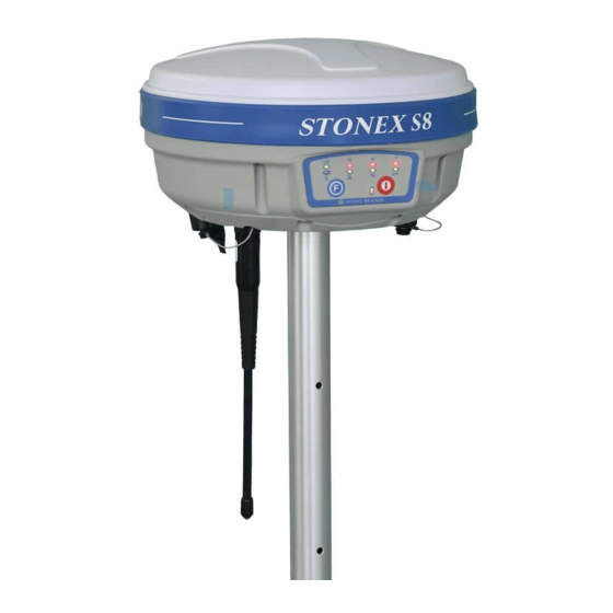
After S8III and S7 Series, S8 gives new opportunities to exactly fit the Surveyor’s needs, featuring top performances with a budget price. Like the elder brother S8III, S8 is able to receive both of GPS signal frequencies and also satellite signals from GLONASS, GALILEO, COMPASS and SBAS, so we can correctly speak about a “GNSS receiver”. - Page 5 Chapter I: A brief introduction of S8 III to-day work. STONEX provides two year of warranty to S8 receivers . It should be noted that high power ® signals from a nearby radio or radar transmitter can overwhelm the receiver circuits. Low power transmitter like those used in cell-phones do not normally interfere with receiver’s...
-
Page 6: Chapter Ii: S8 Mainframe
Chapter II: S8 III mainframe Chapter II: S8 mainframe II.1 The outlook of mainframe The mainframe has an almost cylindrical shape, with a base larger than the height. There are three parts: an upper cap, a rubber loop and the main structure. The upper cap protects the GNSS antenna placed inside. - Page 7 TNC connector for GPRS/GSM antenna 5pins Lemo port for external datalink connection Battery housing Front panel Built-in radio module 7pins Lemo port for data transfer. TNC connector for UHF radio antenna Fig. 2.2 - S8 components and ports Fig. 2.3 - 5-pins LEMO port...
-
Page 8: Ii.3 The Installation Of Battery
II.3 The installation of battery SIM card slot MicroSD card slot Battery Battery housing Fig. 2.5 - S8 battery housing Under the place for the battery, there is a slot for SIM card, which is necessary to have when a... -
Page 9: Ii.4 Indicator Leds And Instrument Setup
9. internal power led 10. Function Key 11. Power Key Fig. 2.6 - S8 keys and indicator leds The functionality as follows, from left to right: SATELLITE led (green): It shows the amount of locked satellites; when the receiver links one or more satellites signal, it will start to blink every 30 seconds for a number of times equal to the number of locked satellites. - Page 10 1 Hz it blink anyway at 1 Hz. Fig. 2.8 - S8 static led ROVER led (red): Rover led is on when the receiver is working in rover mode.
- Page 11 This led is on when UHF internal radio is selected as RTK datalink. It is blinking when is transmitting data in base mode or receiving data in rover mode. Fig 2.12 - S8 internal radio led GSM/GPRS led (green): This led is on when GSM/GPRS module is selected as RTK datalink. It starts to blink when there is data transfer ongoing ( download in rover mode and upload in base mode).
- Page 12 This led is on when external datalink is selected as RTK datalink. It starts to blink when there is data transfer ongoing( download in rover mode and upload in base mode). Fig 2.14 - S8 external radio led POWER led (green and red) : It includes three kind of status: 1.
- Page 13 Chapter II: S8 III mainframe F Key : Function key It can switch the working mode (static, base or rover) and RTK datalink (built-in radio, external radio or GPRS/GSM). Switch working mode: Power on the receiver while pressing F key in the meantime, wait until all lights flash, then release both buttons.
-
Page 14: Chapter Iii: S8 Standard Accessories
III.1 The case of S8 There are two kinds of S8 cases: Rover case and Base case. The inner layout of the Base case and Rover case is different. Base case contains also the basement and tribrach for fixing the base on a tripod and a 40 cm pole for put the base higher, while Rover case included the bracket for the controller. - Page 15 Chapter III: S8 III standard accessories Fig. 3.2 - S8 internal case of Rover Fig. 3.3 - S8 Base case...
-
Page 16: Iii.2 Power Supply
Chapter III: S8 III standard accessories III.2 Power supply Batteries The standard configuration contains two batteries, a slot for charging batteries (named “charger” for simplicity) and an adaptor. The battery are “lithium-ion” battery (7.4 V - 2500 mAH): a technology which has an higher energy-to-weight ratio with respect to NiCd or NiMh batteries, no memory effect, and slow self-discharge when not in use. -
Page 17: Iii.3 The Antennas
40, 37,5 and 34 cm. They are suitable for field surveying, light and durable. The gain is 2.15 dBi. Fig. 3.6 – built-in radio antenna (not in scale) S8 adopts a GPRS/GSM all-direction transmitting and receiving antenna with a frequency in the... -
Page 18: Iii.4 Cables
20 cm, the gain is 2 dBi . Fig. 3.7 – Gprs/gsm antenna (not in scale) For S8, it is possible to use like additional accessory (not included in the standard configuration) a high-gain UHF all-directional transmitting antenna for base setup. The available ranges are: 410-430 MHz, 430-450 MHz and 450-470 MHz. - Page 19 Chapter III: S8 III standard accessories LEMO port) and computer (by a serial and USB port) used for transferring the static data, setting the receiver, updating the firmware and the license. Fig. 3.9 - Multi-function communication cable Auxiliary cable External power supply cables can be ordered and used to connect an external battery (red and black clips) to the receiver (small 5-pin LEMO):...
-
Page 20: Iii.5 Other Accessories
Chapter III: S8 III standard accessories III.5 Other accessories The other accessories are: 2.45 m retractable pole, 40 cm supporting pole, two kind of brackets depending on the controller, tribrach with plummet, tripod (wood or aluminum, with quick or twist clamps), connector between receiver and tribrach, and measuring tape. -
Page 21: Iii.6 Controller Getac Ps236
Fig. 3.15 – Tribrach and adapter with optical plummet Fig. 3.16 – Connector between tribrach and receiver Fig. 3.17 – Measuring tape. III.6 Controller The S8 can usually be provided with two model of handheld: Getac PS236 or Stonex S3... - Page 22 Chapter III: S8 III standard accessories controller in the standard configuration. Anyway the controller is not part of the accessories for S8, it must be purchased separately. Fig. 3.18 - Getac PS236 controller Fig. 3.19 – Stonex S3 controller...
-
Page 23: Chapter Iv: S8 Configuration
Chapter IV: S8 III configuration Chapter IV: S8 Configuration IV.1 The installation of base and rover BASE ROVER TX / RX ANTENNA TX / RX ANTENNA Fig. 4.1 - Base and rover configuration Installation of Base Install the tripod on the chosen location, level it and attach the receiver into tribrach. -
Page 24: Iv.2 The Configuration By Using Keys
Switch on the handheld and start the software for the radio channel configuration and inserting the base coordinates, otherwise it is possible to make the settings by Stonex Assistant pc software. Installation of Rover Fix the bracket on the pole, fix the handheld into the bracket, put the rover on the pole and attach receiving radio antenna into the port “UHF”... - Page 25 Chapter IV: S8 III configuration Fig. 4.2 - S8, all led blinking at the same time Now every time you press F key, the STATIC/ROVER/BASE lights will switch on in the corresponding order. You can select three different red lights, each of them refers to one working mode.
-
Page 26: Iv.3 Standard Operation Of Leds
4. Internal UHF Radio 5. GPRS\GSM module 6. External radio Fig. 4.4 - S8 summary of data-link led The next time you will switch on again the receiver, the working mode and data-link will be the last selected. If you prefer, you can select the correct data-link by handheld software. -
Page 27: Iv.4 How To Measure The Antenna Height
Chapter IV: S8 III configuration Base mode The BASE, power led and selected datalink (UHF, GPRS/GSM or EXTERNAL) will keep lighted. When satellites fulfill the conditions, the base will enter into the transmit mode and start to send data through the datalink. The datalink green led flashing every one second means the base transmit normal. - Page 28 STONEX GPS Processor you have to specify the correct antenna height before processing ® .DAT data or exporting it into RINEX format. The same if you are using STONEX Assistant for ® converting .DAT into RINEX. Please read the specific manual of STONEX GPS Processor, it ®...
-
Page 29: Iv.5 How To Download Static Data
Chapter IV: S8 III configuration IV.5 How to download static data For a correct connection between receiver and PC, follow the procedure described below. By using a different procedure it may be very difficult to make a connection. At first turn on the mainframe, then connect the cable to the communication interface of the receiver (7-pins Lemo port), then insert the USB port in the PC. -
Page 30: Iv.6 Registration Of The Receiver
You can copy the original file to PC and if necessary modify the file names. As Fig. 4.7, for example, shows, .INI file is the configuration file stored in the memory of S8. You can open also the “CONFIG.INI” file as a simple text file and set some parameters of static mode: sampling frequency, minimum elevation angle, etc. -
Page 31: Chapter V: Stonex Assistant For S8
Assistant is a tool which is conceived for aiding the user to make easier different ® operations with the receiver S8. It is contained in the bundle CD, the actual version is 1.49. Fig. 5.1 – Main page of Stonex Assistant... -
Page 32: Start Stonex Assistant On Your Pc
S8 after get PC connection. V.1 Start Stonex Assistant on your PC. Connect the S8 to the PC USB port using Lemo7 – USB/Serial cable. Switch on the receiver; automatically the program should search the COM port where the receiver is connected. - Page 33 When you find the right COM port, you should see the screen shown in Fig 5.3 that show you in the main window the system information. Fig. 5.3 – Information page of Stonex Assistant From the showed information you can understand about: the battery level, the firmware version of GNSS board, the antenna information, the firmware of radio and gprs internal device, the free disk space and the current working and datalink setting.
-
Page 34: Settings
CONFIG .INI file and modifying it by hand in a text editor (not recommended). You can set the survey working mode (Static, Dynamic --> Base/Rover) and the kind of datalink (NETWORK, UHF, EXTERNAL, BLUETOOTH) of S8 (see the red rectangle in Fig. 5.4). -
Page 35: Static Data Survey
Chapter V: Stonex Assistant for S8 DefRadSettings Some definitions of working mode: Static: is the stand-alone station that collect raw observations and need a post-processing in office for getting accurate results. Base: is the fixed GPS station used to provide differential corrections to the mobile GPS receiver. - Page 36 Chapter V: Stonex Assistant for S8 DefRadSettings Fig. 5.5 – Static working mode From here you can control following data settings: Cut Angle : Define the minimum elevation of satellite to be collected in order to avoid noisy satellites (suggested value between 20° and 10°).
-
Page 37: Dynamic Working Mode
Chapter V: Stonex Assistant for S8 DefRadSettings Automatic Record : Start automatic GPS static survey after power on. For static survey this option strictly NEED to be enabled in Stonex Assistant. When the configuration is completed, click on button “Save” to update the Receiver configuration. -
Page 38: Base Coordinates Setting
Elevation mask: Define the minimum elevation of used satellite to be collected in order to avoid noisy satellites (suggested value between 20° and 10°). Record Raw data: to record raw data inside memory of S8. Using Glonass: to enable/disable Glonass reception. - Page 39 Chapter V: Stonex Assistant for S8 DefRadSettings Fig. 5.7 – Base Setting window Inside this form, you can choose if the Base coordinates must be inserted manually ( “Start Up By Specific Position” ) if known, or calculated from GPS observations ( Automatic Start Up By Single Position) if unknown.
- Page 40 Chapter V: Stonex Assistant for S8 DefRadSettings Fig. 5.8 – Automatic Start Up By Single Position Click “OK” to confirm your data entry. Start Up By a Specific Position: By choosing the “Start Up by Specific Position” it is possible to introduce directly the...
-
Page 41: Data Link
Chapter V: Stonex Assistant for S8 DefRadSettings Fig. 5.9 – Start Up by a specific position V.2.3. Data Link Here you can select the type of datalink used to get/provide differential corrections. Four different options are available for “rover” mode: GPRS/GSM modem (“Network”), internal radio (“UHF”), external radio or external device (“External”), Bluetooth device (“Bluetooth”), or... - Page 42 Chapter V: Stonex Assistant for S8 DefRadSettings Fig. 5.10 – Network If you will click on the button “Settings” (red rectangle in Figure 5.10), a new form will open. From here you can choose the type of connection:...
- Page 43 In the base configuration he should only enable the automatic connect, not other set is required, it is also necessary to switch on first the base and then the rover. Anyway you can also refer to a specific tutorial regarding how to set a direct call between two S8.
- Page 44 Chapter V: Stonex Assistant for S8 DefRadSettings Fig. 5.12 – CSD Settings PPP: For VPN (Virtual Private Network) users, where each SIM card has assigned a static IP address, or for a connection with a single CORS station. Therefore the rover can be connected directly to the base via entering the base IP.
- Page 45 Chapter V: Stonex Assistant for S8 DefRadSettings Fig. 5.13 – PPP Settings NTRIP: It is the most common. Connection to a provider using data transfer in accord with NTRIP protocol by internet GPRS connection. If you select this option, you have to insert the following data in the right side (see Figure 5.14):...
-
Page 46: Uhf Radio
Chapter V: Stonex Assistant for S8 DefRadSettings Fig. 5.14 – NTRIP Settings GGA Upload: input window provide the interval of NMEA GGA string upload, this string contains the rover coordinates that must be sent to the CORS or base, the proper interval depends on the base. -
Page 47: External
Chapter V: Stonex Assistant for S8 DefRadSettings Fig. 5.15 - UHF Radio Settings Frequency setting: insert the frequency, expressed in MHz, of the radio link associated to each channel. There are 8 channels available in the internal UHF radio . -
Page 48: Bluetooth
Chapter V: Stonex Assistant for S8 DefRadSettings insert the baud rate of the external radio: Fig. 5.16 - External radio baud rate Click on button “OK “ to confirm. V.2.3.4. Bluetooth This option give us the possibility to use Bluetooth device for RTK data exchange. In this case... -
Page 49: No Datalink
Fig. 5.17 - Bluetooth When you have completed all your selection, please click on “Save” button and the configuration will be stored inside S8 memory. V.2.3.5. No Datalink – only for Rover This option has to be selected if customer don’t need any kind of corrections. -
Page 50: Nmea Output String
Chapter V: Stonex Assistant for S8 DefRadSettings useful for example if the external device is an external radio, but the customer knows that can be too far for receiving the radio signal, so he can put a SIM card inside his rover and try a direct GSM call to the base, this is an example but there can be others application of this functionality. -
Page 51: Import Data
V.3 Import Data This section of the Assistant allows the user to download raw data from S8 memory to Pc, instead of doing manual copy of files. After connecting the receiver click on “Import Data”: a... - Page 52 3 Download Fig. 5.20 – Import Data window Inside this window you can see all files saved in the memory of S8 (excluding the configuration file), which are files with raw GPS measures. By checking only one box or more at the left of each file, you can select it for download operations.
-
Page 53: Serial Port Forwarding
Chapter V: Stonex Assistant for S8 DefRadSettings Figure 5.21 : Fig. 5.21 – Edit Antenna Height window. In the “Edit Antenna Height” menu you can modify the point name, insert the correct antenna height in meters and specify how the height was measured (“Measure Mode” box), there are... - Page 54 Chapter V: Stonex Assistant for S8 DefRadSettings Port forwarding allows the configuration of the GNSS OEM module, UHF module and GPRS module directly. This functionality is valid only for DB9 serial port connection from 5-pin Lemo. Click on “Serial Port Forwarding”: a new window is opened as in Fig. 5.22.
-
Page 55: Register The Receiver
2050, it means that the license is already permanent. b) In the “input authorization code” window you can insert the new temporary or permanent code provided by Stonex. Click on “Enter” to confirm. A confirmation box is... -
Page 56: Firmware Update
Chapter V: Stonex Assistant for S8 DefRadSettings opened, push “Confirm” to allow the new code installation. If your code is expired, please ask to your local dealer/agent. V.6 Firmware update Click on “Firmware Upgrade” button and a new window as in Fig. 5.24 is opened. Then click on “Upgrade”... - Page 57 Chapter V: Stonex Assistant for S8 DefRadSettings If Stonex will release a new firmware, you will receive a communication from your local dealer/agent. In any other case before doing this operation please ask to the technical support of your dealer or of Stonex Support office.
-
Page 58: Appendix 1: Default Radio Settings
Appendix 1: Default Radio Settings Appendix 1: Default Radio Settings S8 uses a single UHF radio to cover the different the whole band 410-470 MHZ . Preset values is done directly from Stonex Europe in accord to the following tables :... - Page 59 Appendix 1: Default Radio Settings Rate Channels 1 channel 464.500 2 channel 464.600 3 channel 464.450 4 channel 464.650 5 channel 464.400 6 channel 464.700 7 channel 465.350 8 channel 466.750 Tab. 6.3 – Internal radio default frequency (MDC)
-
Page 60: Appendix 2: Self-Check Procedure
ON if GNSS OEM module pass the test; FLASH if GNSS OEM module fails the test If you have noticed at least one problem during self-check, please contact your local dealer or email to support@stonex.it After the self-check procedure the receiver will turn on and begin to work normally. -
Page 61: Appendix 3: Technical Specifications
Appendix 3: Technical Specifications Appendix 3: Technical Specifications GNNS module specifications (*): Channels: 120 Satellite signals tracked: GPS: Simultaneous L1, L2, L2C. GLONASS: Simultaneous L1, L2. GALILEO: E1. GIOVE-A, GIOVE-B: test. COMPASS: reserved SBAS. ... -
Page 62: Connection Devices And Protocols
Appendix 3: Technical Specifications Default rate: 1Hz Time to First Fix Cold Start < 50 s Hot Start < 35 s Signal Reacquisition L1 < 0.5 s (typical) L2 < 1.0 s (typical) Time Accuracy 20 ns RMS ... -
Page 63: Radio Module
Appendix 3: Technical Specifications Reference outputs: CMR, CMR+, RTCM 2.3, RTCM 3.0, RTCM 3.1. Navigation outputs: GGA ZDA GST GSV GSA GGK GLL RMC VTG Radio module Internal transmitting and receiving radio: MDS TRM 450 Frequency range available: 410-470 MHz. ... -
Page 64: Physical Specification
Appendix 3: Technical Specifications Working time in RTK rover mode: typically 4 hours. Charge Time: typically < 7 hours. Power consumption: < 3.8 W. Remaining time with battery light blinking: 1 hour. Physical specification: Size: Height 96 mm x Diameter 186mm. 60 mm from the center of the rubber loop to the bottom. -
Page 65: Appendix 4: Copyrights, Warranty And Environmental Recycling
Customer by any STONEX representative in connection with ® Customer’s purchase of the Product. No change to the conditions of this Limited Warranty is valid unless it is made in written form and signed by an authorized STONEX supervisor. ® STONEX Europe warrants that its Products: ®... -
Page 66: Shipping Policy
Limited thirty (30) days or Warranty Period of the Product in which they are installed, whichever is longer. Faulty Parts or Products replaced under this Limited Warranty shall become property of STONEX Europe. ® All products that have to be repaired have to be returned to our technical representative... -
Page 67: Firmware/Software Warranty
Acceptance of returned merchandise is final only after inspection by STONEX Europe. ® Above terms and policies shall apply as for hardware. Dealers needs to follow STONEX Europe ® repair/service procedure (see appendix 4) to achieve a better and prompt service result. - Page 68 AFFILIATES AND SUPPLIERS DO NOT WARRANT THAT OPERATION OF THIS PRODUCT WILL BE UNINTERRUPTED OR ERROR FREE; AS DO ALL ELECTRONICS AT TIMES. IF THIS PRODUCT FAILS TO WORK AS WARRANTED ABOVE, CUSTOMER’S SOLE AND EXCLUSIVE REMEDY SHALL BE REPAIR OR REPLACEMENT. IN NO EVENT WILL STONEX , ITS ®...
-
Page 69: Instruments
(2) If dealer wants to repair an instrument under warranty period on their site: 1) If dealers do not have the part in stock they have to send an official order to STONEX ®... -
Page 70: Environmental Recycling
( refund will be done only after check of the failure part and final approval of STONEX Europe). ® (3) If the instrument needs to be sent back to STONEX Europe for repair/replacement, ® dealer/customer has to send to STONEX Europe a “Returned Merchandise Authorization... -
Page 71: For Countries Outside European Union (Eu)
Appendix 4: Copyrights, warranty and environmental recycling FOR COUNTRIES OUTSIDE EUROPEAN UNION (EU) The treatment, recycling, collection and disposal of electric and electronic devices may vary in accordance with the laws in force in the Country in question.
Need help?
Do you have a question about the S8 and is the answer not in the manual?
Questions and answers