
Related Manuals for Comtek BST-75


Summary of Contents for Comtek BST-75
- Page 1 BST-75 OPERATOR’S MANUAL (72-76 MHz) Synthesized Base Station Transmitter 357 West 2700 South • Salt Lake City, Utah 84115 • Phone: (800) 496-3463 • Fax: (801) 484-6906 • www.comtek.com...
-
Page 2: Table Of Contents
Audio Input Connections ..........Audio Adjustments ..........Audio Processing Circuit .......... Front and Rear Panel Facilities ........Frequency Information .......... Accessories ............10-11 Specifications ............Warranty and Service ..........® © 2005 COMTEK All rights reserved Printed in U.S.A. 11-02-09... -
Page 3: Introduction
The audio processing circuit produces full fidelity frequency response from 80 Hz to 10 kHz with very low residual F.M. noise and distortion. To accommodate a greater variety of receivers, the BST-75 can operate with non-companded receivers or with companded receivers for higher fidelity sound reproduction with a signal-to-noise ratio of up to 100 dB. -
Page 4: Operating Instructions
OPERATING INSTRUCTIONS Equipment Placement If the BST-75 base station is to be rack mounted, a remote antenna must be used. The base station should be mounted away from equipment that uses large power transformers to reduce 60 Hz hum possibilities. -
Page 5: Remote Antenna
COMTEK’s Technical Support Services. Integral Screw-in Whip Antenna If the BST-75 base station transmitter is to be used outside of the traditional rack-mounted environment for stand-alone mobile type applications, the screw-in whip antenna (TWA-75) should be used. -
Page 6: Audio Input Connections
OPERATING INSTRUCTIONS Audio Input Connections The BST-75 base station transmitter uses an XLR-3F connector with a “Combo” phone jack. The XLR portion of the connector will accept a true balanced or unbalanced line level signal up to +20 dBm. The 1/4”... -
Page 7: Audio Processing Circuit
In order to accommodate a greater variety of receivers, the BST-75 transmitter incorporates the option to operate with receivers that have companded or non-companded audio processing. -
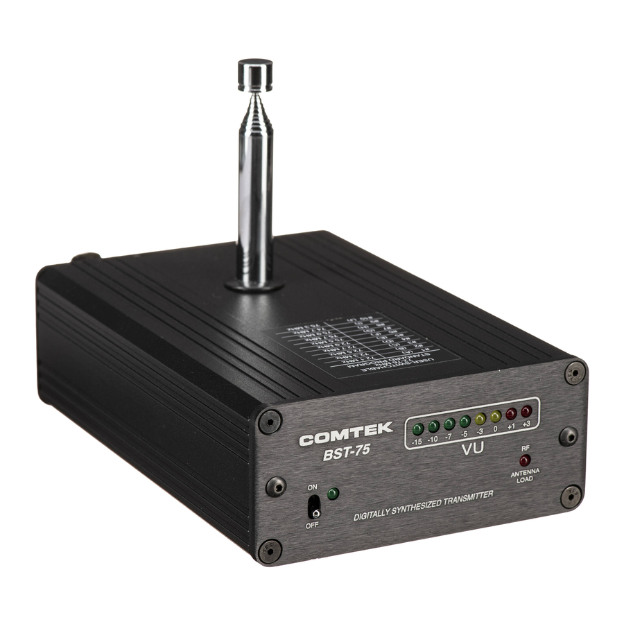
Page 8: Front And Rear Panel Facilities
VU METER: Displays the audio level being used for modulation. (See Audio Adjustment Section.) ANTENNA INDICATOR: Flashes when transmitter detects coaxial cable shorts and open conditions, bad antenna load. RACK-MOUNTING SCREWS: Used for mounting BST-75 to rack-mounting panels. Page 6... - Page 9 BST-75 REAR PANEL POWER INPUT JACK: Requires 12V AC at 200 mA. Will also accept 12V DC with either positive or negative center pin (for field operation only). CHANNEL SELECTOR SWITCH: Selects the frequency on which the transmitter will operate. (See Frequency Information Section.) EXTERNAL ANTENNA JACK: BNC connector provides a standard 50 ohm RF output for use with an external antenna.
-
Page 10: Frequency Information
BST-75 FREQUENCY INFORMATION USER-SWITCHABLE AVAILABLE 72-76 MHz “FLASH MEMORY” STANDARD CHANNELS NON-COMPANDED COMPANDED CHANNELS CHAN FREQ CHAN FREQ CHAN FREQ CHANNEL FREQUENCY 72.02 MHz 72.80 MHz 75.58 MHz A #1 72.1 MHz 72.04 MHz 72.82 MHz 75.62 MHz 72.3 MHz 72.06 MHz... -
Page 11: Frequency Selection
BST-75 FREQUENCY INFORMATION Frequency Selection The BST-75 transmitter comes from the factory on 10 standard manually selectable channels. Other group frequencies are available from the 88 “Flash Memory” programmable channel list and have been coordinated for simultaneous operation. These group frequencies can be programmed for use with the manual 10-channel selectable user-switch. -
Page 12: Accessories
BST-75 ACCESSORIES Included Accessories 1. C-75 Carrying case 2. BST-75 Operator’s manual 3. TWA-75 Telescoping whip antenna 4. AP-12VAC Power adaptor (115V AC Input) 5. BST-75 Base station transmitter Page 10... - Page 13 BST-75 ACCESSORIES Optional Accessories 1. RDA-2B Remote dipole antenna 2. PRA Phase-Right coaxial antenna 3. PRA Phase-Right antenna mount 4. HM-100 1/4” Behind-the-neck directional boom microphone 5. RMK 75-4 Quad rack-mount face plate 6. RMK 75-2 Double rack-mount face plate 7.
-
Page 14: Specifications
BST-75 SPECIFICATIONS Modulation Limiter: Audio Inputs: • Line level balanced input Peak compressor type with high linear overload protection 0 dBm for 80% modulation (+20 dBm max) (25 dB). Attack time less than • Electret mic unbalanced input 1 ms, recovery time 10 ms... -
Page 15: Warranty And Service
WARRANTY COMTEK warrants this product to be free from defects in workmanship and material under normal use and conditions for a period of one year from date of original purchase. Items such as batteries, neckloops, and cords are not covered by the warranty. Damage due to misuse, ill treatment and unauthorized modification and repairs are not covered by this warranty. - Page 16 357 West 2700 South • Salt Lake City, Utah 84115 • Phone: (800) 496-3463 • Fax: (801) 484-6906 • www.comtek.com...
Need help?
Do you have a question about the BST-75 and is the answer not in the manual?
Questions and answers