Table of Contents
Advertisement
Advertisement
Table of Contents

Related Manuals for Verint S1100

Summary of Contents for Verint S1100
- Page 1 S1100 User Manual...
-
Page 3: User Manual
S1100 Firmware Release 3.30 User Manual Verint Video Solutions... - Page 4 HealthCheck, Lanex, Loronix, Loronix Video Manager, MotionTrack, microDVR, nDVR, netDVR, Powering Actionable Intelligence, SmartSight, and Video Manager are trademarks of Verint Systems Inc., its subsidiaries or affiliates. All other registered trademarks, trademarks, and any associated logos are the properties of their respective owners.
- Page 5 Warning: If you connect multiple S1100 units on the same 24V AC power source, always wire them the same way: The red power wires (VIN) of all units must be on the same terminal or lead of the AC power source.
- Page 6 Verint Video Solutions...
-
Page 7: Table Of Contents
Who Should Read this Manual ........x How to Use this Manual ..........x Contents ..............x Conventions ............xi Related Documentation ........xii Related Verint Video Solutions Products ....xii About Us ..............xii Warranty ..............xiv Chapter 1 Overview ........... 1 About the S1100 ............2 Security .............. - Page 8 Contents Configuring a Point-to-Point Repeater ......27 Installing the Equipment ...........28 Installing the S1100 Units ........29 Performing the RS-422/485 Serial Connection ..31 Adding an Antenna ..........33 Configuring the I/Os ..........34 Audio ..............34 Alarms ..............36 Performing a Hardware Reset ........37 Status LED ..............37 Chapter 4 Using the Configuration Assistant ....
- Page 9 S1100 User Manual Appendix G Technical Specifications ......87 Glossary ..............91 Index ................97 Compliance ............... 103 Verint Video Solutions...
- Page 10 Verint Video Solutions...
-
Page 11: Preface
Preface The S1100 User Manual presents the information and procedures for installing, configuring, and using the ® SmartSight S1100 wireless video systems. Verint Video Solutions... -
Page 12: Who Should Read This Manual
Who Should Read this Manual This manual is intended for managers, engineers, and technicians who will use the S1100 units. It provides conceptual information on how to configure, install, and operate the units. This manual assumes that you are familiar with:... -
Page 13: Conventions
(DTE) and data communication equipment (DCE). D. Surge Protection—Describes how to protect the S1100 unit from voltage and current surges. E. RF Contact between Masters—Explains how to ensure that two master units “see” each other. -
Page 14: Related Documentation
Related Verint Video Solutions Products You can use the S1100 units with the S3100 outdoor wireless bridge. For more details about this product, visit our web site. For pricing information, call your dealer. - Page 15 Support If you encounter any type of problem after reading this manual, contact your local distributor or Verint Video Solutions representative. You can also use the following sections on our web site to find the answers to your questions:...
-
Page 16: Warranty
Product is not defective within the terms of the warranty, Buyer shall pay all handling and transportation costs. Verint Systems may, at its option, elect to correct any warranty defects by sending its supervisory or technical representative, at its expense, to customer’s plant or location. -
Page 17: Chapter 1 Overview
Overview The S1100 is a professional video transmission product designed for the CCTV (closed circuit television) market. It allows digital video transmission over multiple license-free bands. It delivers high-quality MPEG-4-based video at 30 frames per second in NTSC (25 in PAL). This wireless system is built on open standards to provide long-term investment protection. -
Page 18: About The S1100
(4800 baud, 8 data bits, no parity, 1 stop bit). The S1100 covers the 2.4 GHz and 5 GHz frequency bands in North America and Europe. You can buy 12V DC and 24V AC units. A unit pair does not need to have the same input voltage. -
Page 19: Shipment
S1100 User Manual The S1100 units can have the following video resolutions and maximum frame rates (in frames per second): Resolution Number of Number of lines Maximum frame columns rate NTSC/PAL NTSC NTSC QCIF 2CIF 2CIFH 4CIF All lines 2/3 D1... -
Page 20: Casing Description
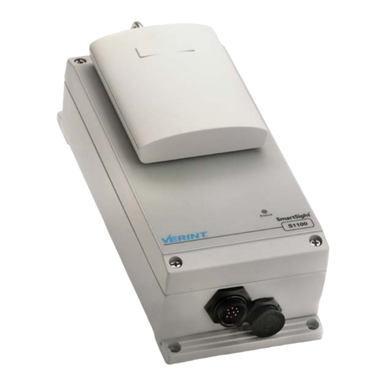
1A (12V DC) or 30 VA (24V AC). Casing Description The S1100 electronics are enclosed in a weather-tight cast aluminum module. All cable entries are mounted on the underside of the module to maintain its weatherproof properties. -
Page 21: System And Rf Planning
In all cases, follow the recognized RF installation practices. One radio system is a receiver and a transmitter using the same wireless passkey. Verint Video Solutions... -
Page 22: Frequency Bands And Channels
2: System and RF Planning Frequency Bands and Channels The S1100 supports communications in the following frequency bands, in North America and Europe: 2.4 GHz OFDM, also known as 802.11g 5 GHz OFDM, also known as 802.11a 2.4 GHz Band The 2.4 GHz band provides 11 channels in North America and... -
Page 23: Wireless Cells
S1100 User Manual In North America, nine channels are available in the 5 GHz band, all non-overlapping and for indoor or outdoor use. The center frequencies of these channels are: Channel Frequency (GHz) Channel Frequency (GHz) 5.26 5.745 5.28 5.765 5.30... - Page 24 Cell2, for the transmitters receivers When planning your wireless systems, you have to take into account the firmware versions of the involved units: The two S1100 units making up a pair must have the same firmware version. Verint Video Solutions...
-
Page 25: Tpc
V2.60 V3.20 V3.30 As far as updating the firmware, you should: 1. Update the firmware of all S1100 pairs, starting with the remote unit. 2. Change the IP address of the computer running SConfigurator (refer to the S3100 User Manual). - Page 26 2. The starting order delay ensures that colocated masters will not select a frequency channel at the same time, therefore minimizing the possibility that they choose the same one. For more information about the starting order, see page 45. Verint Video Solutions...
-
Page 27: Colocated Systems
S1100 User Manual 3. The unit scans the available frequencies (based on the selected country) and automatically selects a channel. In the selection process, channels already used by colocated masters will be discarded at first. 4. The unit listens for 60 seconds on the selected channel to detect possible radar interference. -
Page 28: Distance Limitations
Up to Three Point-to-Point Systems As long as you follow the recognized RF installation practices, you can colocate three S1100 point-to-point systems without special consideration for antenna placement and type. You simply have to: 1. Assign a unique wireless passkey to each system. - Page 29 Up to Six Point-to-Point Systems (< 180° Coverage) You can install up to six S1100 receivers on the same side of a building or on the same mast, with their antennas pointing within the same direction (within a 180° angle of each other).
-
Page 30: Ghz Band In North America
Up to Nine Point-to-Point Systems As long as you follow the recognized RF installation practices, you can install up to nine S1100 point-to-point systems in colocation mode, on the same pole or on different sides of a building, without sharing channels. -
Page 31: Ghz Band In Europe
Up to 16 Point-to-Point Systems (< 180° Coverage) You can install up to 16 S1100 receivers on the same side of a building or on the same mast. To do so, the receivers must be pointing within the same direction (within 180° direction of each other). - Page 32 Video Solutions project engineering group for assistance. Supported Setups The following colocated systems are supported in the 5.40–5.725 GHz band: A point-to-point repeater for one or more pairs of S1100 units, with or without hidden nodes. The two S3100 master units see each other. S3100...
-
Page 33: Rf Planning
You cannot install the following colocated systems in the 5 GHz band in Europe: A point-to-point repeater with a point-to-point link. In this setup, there are two masters that do not see each other, S3100 2 and S1100-R 2, while the two receivers do. S1100-T 1 S1100-R 1 S1100-R 2... -
Page 34: Location Evaluation
Because the reliability of such an installation is highly unpredictable, Verint Video Solutions does not recommend it. A path free of any obstacle is called an RF line-of-sight path. To establish an RF line-of-sight path, you must take into account the beam width of the radio signal transmitted between the two antennas. - Page 35 RF line of sight between them (that is, 53 feet for the Fresnel zone plus 29 feet for the earth curvature effect). For help, consult the Verint Video Solutions project engineering group. A common problem encountered in the field and related to the 0.6 F1 clearance rule is building obstruction.
-
Page 36: Antenna Requirements
2: System and RF Planning Antenna Requirements Verint Video Solutions offers many antennas to meet various distance requirements. You have to consider many factors when choosing an antenna, including the distance to cover, the RF bit rate, the radiated power (EIRP), and the frequency band used. For systems located in North America on the 5 GHz band, you can use the Wireless Distance Calculator located on our web site (Tools &... -
Page 37: Interference
Fortunately, you have ways of adapting your setup to avoid interference: RF channel selection—In the 2.4 GHz band, the S1100 has 11 or 13 channels to choose from. In case of interference, it is recommended to change channel until you find a clean one. - Page 38 Verint Video Solutions...
-
Page 39: Configuring And Installing The Unit
Configuring and Installing the Unit To prepare your S1100 system for operation, the steps to follow are: Basic configuration, mainly for radio frequency (RF) and serial connection Physical installation in its final location Alarm and audio configuration, if required Two types of applications are covered:... -
Page 40: Cable For Power, Video, And Serial Data
For the detailed pinout, see page 68. Serial Port The S1100 integrates one multipurpose serial port. This port is used for system configuration and data communication: pan-tilt-zoom (PTZ), access control, or other. By default, the port automatically detects if it is connected to an RS-232 or RS-422/485 serial device. -
Page 41: Computer Requirements
RS-422/485 equipment on the terminal block. Warning: At any time there must be only one serial device connected to the S1100 unit. For instance, when configuring the unit, you must unplug any RS-422/485 device from the terminal block. - Page 42 Ensure that the repeater mode is disabled. Enter the wireless passkey of the units. Write down the values of the configuration parameters in the form located at the end of the S1100 Installation Guide. 7. Connect the external antennas, monitor, and camera to the units;...
-
Page 43: Configuring A Point-To-Point Repeater
A point-to-point repeater is used as a range extender for wireless links, when you need a device to retransmit the signals coming from one or many S1100 transmitters to their corresponding receivers. A repeater is made up of two S3100 master bridges. -
Page 44: Installing The Equipment
Enable the repeater mode. Enter a different wireless passkey for each unit. Write down the values of the configuration parameters in the form located at the end of the S1100 Installation Guide. As soon as these settings are saved, the units are not communicating anymore, since they have different wireless passkeys. -
Page 45: Installing The S1100 Units
In such environments, vulnerable connections are those that run for a long distance between the S1100 unit and the connected equipment. For more information, see the “Surge Protection” appendix on page 75. - Page 46 9. Carefully align the antenna of each S1100 unit with that of its corresponding unit (S1100 or S3100) so that they have a clear RF line of sight.
-
Page 47: Performing The Rs-422/485 Serial Connection
Performing the RS-422/485 Serial Connection Most target devices (keyboards, PTZ cameras) that are likely to be linked to the S1100 units use the RS-422 or RS-485 serial protocol. To connect the CAB9P cable to a device in an RS-422 2-wire,... - Page 48 RS-485 2 Wires and the line driver to RS-422 (for details, see page 47). Cable Target device Signal name Wire pair Wire color Signal name Data+ green/black green Data+ Data- black Data- Signal ground brown/black brown Signal ground Signal ground black Signal ground Verint Video Solutions...
-
Page 49: Adding An Antenna
Warning: Even if you are using an external antenna, do not remove the integrated one; otherwise the warranty becomes void. 1. Install the antenna above the S1100 unit. If you bought your antenna from Verint Video Solutions, use the supplied pole mount bracket. -
Page 50: Configuring The I/Os
To program alarms or use the audio features of the unit, you need the CAB8P cable assembly. For detailed pinout information, see page 70. The S1100 supports two inputs and one output. Each signal has a dedicated purpose: Input 1—Either transparent alarm links (default) or PTL (push-to-listen) audio transmission mode. - Page 51 S1100 User Manual Here is a typical PTT/PTL application: Audio Out Audio In In 2 and Gnd Audio Out Audio In In 2 and Gnd Gnd and In 1 signal signal signal signal signals terminals terminals Regardless of the audio mode (PTT/PTL or full duplex), you...
-
Page 52: Alarms
The relay output on the receiver is configured to close the contact between the two output pins (up to 48V at 100 mA) upon alarm activation. Alarm Out+ Alarm Out- Alarm Input 1 Alarm Ground Event sensor Verint Video Solutions... -
Page 53: Performing A Hardware Reset
(listed in Appendix A on page 65). All user-defined values will be lost. Following a reset, you may need to reprogram the S1100 unit for proper operation with the other unit. To perform a hardware reset: 1. - Page 54 The following power-up conditions are abnormal: LED not lit Check the power supply and cabling. If power is — available and the LED stays off, call Verint Video Solutions technical support for assistance. Steady red LED There is an internal error that prevents the —...
-
Page 55: Using The Configuration Assistant
Using the Configuration Assistant The S1100 units come with a proprietary setup tool called the Configuration Assistant. This tool also allows you to see the status of your units. Verint Video Solutions... -
Page 56: Getting Started
(Firmware Upgrades section). With this software tool, you configure the transmitter and receiver S1100 units in a single operation. In a repeater context, you will need SConfigurator, another SmartSight tool, to configure the S3100 bridges. - Page 57 S1100 User Manual 4. Ensure that the proper COM port name is displayed at the left end of the toolbar. 5. To establish the connection with the unit, click Connect. The main Configuration Assistant window appears, holding the Unit Information and Connection Status panes.
-
Page 58: Performing A Basic Configuration
You must assign the proper country to comply to the DFS/TPC regulations, if applicable, and to use the proper set of frequency channels. 3. If your units are part of a repeater system, enable the repeater mode. Verint Video Solutions... -
Page 59: Performing An Advanced Configuration
S1100 User Manual 4. Change the wireless passkey of the units: If the units form a point-to-point system, enter the passkey common to the transmitter and receiver. If the units are in repeater mode, enter two different passkeys. 5. Assign a meaningful name to the units. -
Page 60: General
Repeater Mode—If you set the mode to Enabled, you will have to use the SConfigurator tool, instead of the Configuration Assistant, to subsequently change any wireless parameter; otherwise, the repeater will not work properly. For more information, page 50. Verint Video Solutions... - Page 61 It is the default value. Once the unit is operating properly, Verint Video Solutions strongly recommends to change the configured bit rate from Auto to the actual bit rate of the connection. This way,...
-
Page 62: Video
“hear” its legitimate correspondent. Video The video parameters are: If the content of the Quality field is Low, Medium, or High, the next parameters are unavailable. To change these parameters manually, you have to select the Custom quality. Verint Video Solutions... -
Page 63: Audio
S1100 User Manual Audio The audio parameters are: Serial Port The serial port parameters allowing communication with the target equipment (camera, monitor, and so on) are: If the line driver is forced to the RS-422 setting, you may lose access to the Configuration Assistant since most connections with computers are performed with the RS-232 protocol. -
Page 64: Checking The Connection Statuses
Checking the Connection Statuses The main Configuration Assistant window presents the general connection statuses of the pair of units. You can get more details by clicking the corresponding More button. Wireless The specifics of the wireless status are: Verint Video Solutions... -
Page 65: Video
S1100 User Manual Video The specifics of the video status are: Audio The specifics of the audio status are: Verint Video Solutions... -
Page 66: Serial Port
Serial Port The specifics of the serial port status are: Repeater Consideration If your S1100 units are part of a running point-to-point repeater, you must use the SConfigurator tool, instead of the Configuration Assistant, to change the wireless parameters; otherwise, the repeater will not work properly. For more information about SConfigurator, refer to its user manual. - Page 67 S1100 User Manual 2. Double-click Local Area Connection. The Local Area Connection Status window appears. 3. Click Properties. The Local Area Connection Properties window appears. Verint Video Solutions...
- Page 68 1. In the Windows Start menu, choose Control Panel. 2. If the classic view is enabled, choose Network Selection. In the category view, select Network and Internet Connections, then Network Connections. 3. Double-click your active LAN or Internet connection. Verint Video Solutions...
- Page 69 S1100 User Manual 4. Click Properties. A Properties window appears. 5. In the General tab, select the Internet Protocol (TCP/IP) item, then click Properties. The Internet Protocol (TCP/IP) Properties window appears. Verint Video Solutions...
-
Page 70: Accessing The Cli Of The Unit
To access the CLI, you need a serial connection between the computer and the unit. To access the CLI of a unit: 1. Connect the desired unit to the computer using the CAB9P serial cable. 2. Start the Configuration Assistant. Verint Video Solutions... - Page 71 The CLI has a timeout that is triggered after three minutes of inactivity. When the timeout occurs: You lose access to the command line. The “Thank you for using the Verint Video Solutions CLI” message appears at the command line. The Console window becomes disabled.
- Page 72 Verint Video Solutions...
-
Page 73: Understanding The On-Screen Display
Understanding the On-Screen Display The S1100 receiver units display information on a video monitor. Verint Video Solutions... -
Page 74: Quadrant 2: Smartsight Logo
1 and 4 turn to red and quadrants 2 and 3 become blue/black. Quadrant 2: SmartSight Logo In quadrant 2, when the unit is powering up, the SmartSight logo will be displayed for 30 seconds. Verint Video Solutions... -
Page 75: Quadrant 3: Receiver Settings
422f-d Line driver Quadrant 4: Transmitter Settings Quadrant 4 displays basic S1100-T configuration details, including firmware version, serial port, and RF data. This information is displayed for 30 seconds every time the connection is established with the receiver. For example:... - Page 76 Verint Video Solutions...
-
Page 77: Updating The Firmware
Updating the Firmware You use the SmartSight Configuration Assistant to update the firmware of your S1100 unit. You can download the latest firmware file from our web site (Firmware Upgrades section). Verint Video Solutions... - Page 78 6: Updating the Firmware You can update the firmware of both units making up the S1100 system in a single operation, provided the RF link is stable. You should connect the receiver (the local unit) to the computer, then start by updating the firmware of the transmitter (the remote unit).
- Page 79 S1100 User Manual 3. Click Firmware Update. The Firmware Update window appears. 4. In the Communication Port field, select the COM port used. 5. Click Remote. 6. Click Browse, then select the desired firmware file. 7. Click Update Firmware. The update process of the remote unit starts. It may take several minutes to complete.
- Page 80 Starting firmware upload. The update process has begun. Firmware upgrade request sent. The Configuration Assistant has made a request to the S1100 unit for update. Reception timed-out. Verify that serial cable is properly connected. Check the quality of the cable assembly. If the problem persists, contact Verint Video Solutions technical support.
-
Page 81: Appendix A Factory Default Configuration
Factory Default Configuration Verint Video Solutions... - Page 82 A: Factory Default Configuration The S1100 is programmed at the factory with the following configuration: Type Configuration Serial port Bit rate: 4800 bauds Parity: none Line driver: auto-detected RS-422/485 operating mode: RS-422 4 Wires Video settings Standard: NTSC (North America)
-
Page 83: Appendix B Cable Descriptions
Cable Descriptions The wireless units use the following two cables: CAB9P—Power, video, and serial data communication CAB8P—Audio and alarms Note: To determine the Rx and Tx pins of your equipment, see Appendix C on page 71. Verint Video Solutions... -
Page 84: Cab9P
(that is, PTZ data with the RS-422/485 protocol, or RS-232 communication with the DB-9 connector). The mating side view of the cable is, using the RS-232 signal terminology: CAM4/ (Tx+) (Tx-) (Rx-) VIN RT (Rx+) Verint Video Solutions... - Page 85 S1100 User Manual Here is the pinout of the CAB9P cable: Power VIN_RETURN Black [Red] Red [Black] N.C. (Rx+) Green [Black] N.C. Black [Yellow] (Tx-) N.C. Yellow [Black] (Tx+) N.C. N.C. Black [Blue] N.C. CAM4/MON Blue [Black] Black [Green] (Rx-)
-
Page 86: Cab8P
Audio Out Alarm In 1 Yellow [Black] Alarm Out B Black [Red] Alarm Ground Black [Yellow] Black [White] Alarm In 1 Female mating side where: The other wire of the twisted pair is enclosed in square brackets. Verint Video Solutions... -
Page 87: Appendix Cdte And Dce Connections
Before connecting a SmartSight unit to other serial equipment, you need to determine if they are DTE (data terminal equipment) or DCE (data communication equipment). Here are examples of both equipment types: DCE—SmartSight units, modems DTE—Computers, switches, multiplexers, cameras, keyboards Verint Video Solutions... - Page 88 C: DTE and DCE Connections You need to know the equipment type of the other serial device to connect it correctly to the S1100 unit, which is a DCE. In the following descriptions: Voltage is measured when no data is transferred on the Rx and Tx pins.
- Page 89 S1100 User Manual Data Communication Equipment DCE modules have the following electrical-level setup: Pin number Signal Measured voltage 0 volt -X volts Ground -X volts measured -0 volt measured for the Rx pin for the Tx pin Connecting DTE and DCE When connecting two modules of the same type, you have to cross the data wires to create proper communication.
- Page 90 Verint Video Solutions...
-
Page 91: Appendix D Surge Protection
Voltage and current surges can be induced by lightning strikes or power line transients. In the real world, under the right circumstances, these surges can reach sufficiently high levels to damage almost any electronic equipment. Therefore you need to add protection to your units. Verint Video Solutions... - Page 92 D: Surge Protection The S1100 provides basic surge protection on all electrical lines for both the transmitter and receiver units. If you are installing the equipment in a lightning prone or heavy lightning environment, or in a site where large AC mains power...
-
Page 93: Appendix Erf Contact Between Masters
If the country of operation of your units requires DFS compliance, you must ensure that the master units (S3100 and S1100-R) in colocated cells “see” one another in their permanent location. Such a contact means that RF communication can be performed between each pair of masters, therefore preventing them to choose the same frequency channel. - Page 94 (CLI) of at least one master. For more information about the CLI, refer to Chapter 4 in the S3100 User Manual or to Chapter 4 in the S1100 User Manual. To ensure that two master units see each other: 1. Take down the unit name of MasterB.
- Page 95 S1100 User Manual If MasterB is an S1100, go in the Wireless Status window of the Configuration Assistant. Wait until the connection status is Not Connected or Connected; these statuses occur after Radar Detection. If you do not have access to the connection status of MasterB, wait for the following time period: (starting order of MasterB - 1) multiplied by 80 seconds.
- Page 96 Verint Video Solutions...
-
Page 97: Channels
Separation Between Units Using Adjacent Channels Verint Video Solutions... - Page 98 The guidelines apply to the S1100, S1100w, and S3100 units. In the 2.4 GHz band, the adjacent channel term applies only to the three non-overlapping channels (1, 6, and 11).
- Page 99 S1100 User Manual To help you plan your systems, here are installation scenarios that respect the limitations. These scenarios include the frequency band and channel. Using only 5 GHz channels, all on the same side of a building: 5.8 GHz 5.3 GHz...
- Page 100 There is no minimum separation between any two adjacent units sharing a pole, since they do not use adjacent channels: 5.8 GHz 5.3 GHz 5.3 GHz 5.8 GHz 5.8 GHz 5.3 GHz 5.8 GHz 5.3 GHz 5.8 GHz 43 feet (13m) Verint Video Solutions...
- Page 101 S1100 User Manual Using only 5 GHz channels, all on the same side of a tower. The minimum separation between units using adjacent channels—for example, 56 and 60—is the prescribed 13 feet (4m): 5.8 GHz 5.3 GHz 5.8 GHz 5.3 GHz 13 feet (4m) 5.8 GHz...
- Page 102 The minimum separation of 7.8 feet (2.4m) between back-to-back units is respected: 5.8 GHz 5.8 GHz 5.3 GHz 5.8 GHz 5.3 GHz 5.3 GHz 5.8 GHz 5.3 GHz 5.8 GHz 7.8 feet (2.4m) Verint Video Solutions...
-
Page 103: Appendix G Technical Specifications
Technical Specifications Verint Video Solutions... - Page 104 G: Technical Specifications Here are the S1100 technical specifications: Network RF interface SmartSight SDCF Modulation OFDM Encryption 128-bit AES Data rate 6, 9, 12, 18, 24, 36, 48, and (max. burst rate) 54 Mbps Security SSL-based authentication Video Compression MPEG-4-based Frame rate NTSC: 1–30 fps programmable...
-
Page 105: Verint Video Solutions
S1100 User Manual Europe CE marked EN 300 328-2 V1.2.1 (2001-12) EN 301 893 V1.2.3 (2003-08) EN 301 489-01 V1.4.1 (2002-08) EN 301 489-17 V1.2.1 (2002-08) EN 60950:2000 Verint Video Solutions... - Page 106 Verint Video Solutions...
-
Page 107: Glossary
Glossary This glossary is common to the SmartSight line of products. Verint Video Solutions... - Page 108 Codec (Coder/Decoder) A device that encodes or decodes a signal. Configuration Assistant A proprietary graphical program used to configure and update the firmware of the S1100 units. DCE (Data Communication Equipment) In an RS-232 communication channel, a device that connects to the RS-232 interface.
- Page 109 S1100 User Manual DVR (Digital Video Recorder) A device (usually a computer) that acts like a VCR in that it has the ability to record and play back video images. The DVR takes the feed from a camera and records it into a digital format on a storage device which is most commonly the hard drive.
- Page 110 RS-422 A standard interface approved by the Electronic Industries Alliance (EIA) for connecting serial devices, designed to replace the older RS-232 standard because it supports higher data rates and greater immunity to electrical interference. RS-485 An Electronics Industry Alliance (EIA) standard for multipoint communications. Verint Video Solutions...
- Page 111 S1000w The SmartSight outdoor wireless video transmitter operating on the 2.4 GHz frequency band. S1100 The newest series of secure outdoor wireless video systems (one receiver and one transmitter per system) covering the 2.4 and 5 GHz bands in North America and Europe.
- Page 112 Wireless Cell A group of wireless devices that communicate together on the same radio frequency channel and share the same wireless passkey. Wireless Transmission A technology in which electronic devices send information to receivers using radio waves rather than wiring. Verint Video Solutions...
-
Page 113: Index
DFS 9 cable pinout 70 available 6 configuring 47 manual selection 45 connection status 49 characteristics of the unit 2 hardware setup 34 CIF resolution 3 client boot sequence with DFS 11 defined 8 – colocated cell 11 Verint Video Solutions... - Page 114 9 in the Configuration defined 6 – Assistant 44 setups in Europe 15 – distance limitations 81 display on receiver units. See frequency channel OSD (on-screen display). automatic selection with DFS 9 available 6 manual selection 45 Verint Video Solutions...
- Page 115 S1100 User Manual Fresnel zone 18 message, during firmware full duplex audio 34 update 63 monitor connection 32 gain of an antenna 20 general parameters 44 name of unit 42 – half-duplex bidirectional audio 34 on-screen display (OSD) 57 hardware reset 37...
- Page 116 – Utilities CD xii antennas 81 sequence of boot 9 serial connection to RS-422/485 – device 31 Verint Video Solutions web serial port site xiii cable pinout 69 video – cabling for RS-422/485 31 available settings 2 configuring 47...
- Page 117 S1100 User Manual web site, Verint Video Solutions xiii wireless cell 7 wireless connection status 48 wireless frequency plan 6 wireless parameters 44 wireless passkey in colocated cells 12 in the Configuration Assistant 43 in a single cell 7 wiring scheme...
- Page 118 Verint Video Solutions...
-
Page 119: Compliance
Compliance Verint Video Solutions... - Page 120 (EIRP) is not more than that required for successful communication. Note: The S1100 units require professional installation. They should be installed in a location that would prevent the general population from approaching from 3 feet (1 meter) of the radiating element.
- Page 121 S1100 User Manual Canada Operation is subject to the following two conditions: (1) this device may not cause interference, and (2) this device must accept any interference, including interference that may cause undesired operation of the device. To reduce potential radio interference to other users, the...
-
Page 122: Declaration Of Conformity
H7L 4S4 Canada Declares under sole responsibility that the product: Product name: Wireless video transceiver Model number: S1100-CE-5x, S1100-CE-24 To which this declaration relates is in conformity with the following standards or other documents: R&TTE Directive 1999/5/EC EN 300 328-2 V1.2.1 (2001-12) EN 301 893 V1.2.3 (2003-08) - Page 123 H7L 4S4 Canada Declares under sole responsibility that the product: Product name: Wireless video transceiver Model number: S1100-TR-12VDC-24, S1100-TR-24VAC-24 To which this declaration relates is in conformity with the following standards or other documents: R&TTE Directive 1999/5/EC EN 300 328-2 V1.2.1 (2001-12) EN 301 489-01 V1.4.1 (2002-08)
- Page 124 Verint Video Solutions...
- Page 125 Verint Video Solutions 1800 Berlier Street Laval (Quebec) Canada H7L 4S4...
Need help?
Do you have a question about the S1100 and is the answer not in the manual?
Questions and answers