Table of Contents
Advertisement
Quick Links
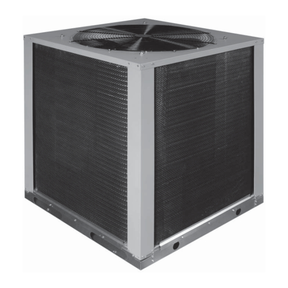
Outdoor Air Conditioner
USER'S INFORMATION AND INSTALLATION INSTRUCTIONS
S3BM-120G High Effi ciency Commercial Split System
IMPORTANT
Read this owner information thoroughly and become familiar with the capabilities and use of your appliance before
attempting to operate or maintain this unit. Keep this literature where you have easy access to it in the future. If
a problem occurs, check the instructions and follow recommendations given. If these suggestions don't eliminate
your problem, call your NORDYNE Servicing Contractor (Service PRO).
Any additions, changes, or conversions required for the appliance to satisfactorily meet the application needs must
be made by a qualifi ed installer, service agency, or the gas supplier using factory specifi ed and approved parts.
These instructions are primarily intended to assist qualifi ed individuals experienced in the proper installation of
this appliance. Some local codes require licensed installation/service personnel for this type of equipment. Please
read all instructions carefully before starting the installation.
DO NOT DESTROY. PLEASE READ CAREFULLY AND KEEP IN A SAFE PLACE FOR FUTURE REFERENCE.
Advertisement
Table of Contents

Related Manuals for Nordyne S3BM-120G


Summary of Contents for Nordyne S3BM-120G
- Page 1 If these suggestions don’t eliminate your problem, call your NORDYNE Servicing Contractor (Service PRO). Any additions, changes, or conversions required for the appliance to satisfactorily meet the application needs must be made by a qualifi...
- Page 2 TABLE OF CONTENTS USER’S INFORMATION INSTALLER’S INFORMATION SAFETY INFORMATION ..........4 SAFETY INFORMATION ..........3 Pressures Within The System .........4 OPERATING INSTRUCTIONS ........3 Labels, Tags and Precautions ........4 Cooling Operation ............3 Brazing Operations ..........4 Heating Operation ...........3 GENERAL INFORMATION ..........4 Operating the Indoor Blower Continuously ....3 Condensing Unit ............4 System Shutdown ............3 Liquid and Suction Lines .........4...
-
Page 3: User's Information
USER’S INFORMATION SAFETY INFORMATION System Shutdown Set the thermostat system switch (See Figure 1) to OFF Safety markings are used frequently throughout this and the thermostat fan switch to AUTO. NOTE: The manual to designate a degree or level of seriousness and system will not operate, regardless of the temperature should not be ignored. -
Page 4: Installer's Information
INSTALLER’S INFORMATION SAFETY INFORMATION Please consult your dealer for maintenance information and availability of maintenance contracts. Please read all Safety markings are used frequently throughout this instructions before installing the unit. manual to designate a degree or level of seriousness and should not be ignored. -
Page 5: Installing The Outdoor Unit
Minimum Circuit Ampacity CONNECTING REFRIGERANT TUBING Electrical wiring to the equipment must be compatible and BETWEEN THE INDOOR AND OUTDOOR in compliance with the minimum circuit ampacity listed UNIT on the outdoor unit data label. General Maximum Fuse/Circuit Breaker Size Once outdoor and indoor unit placement has been Circuit protection for the outdoor unit must be compatible determined, route refrigerant tubing between the... -
Page 6: Electrical Requirements
ELECTRICAL REQUIREMENTS Line Voltage • Electrical power wiring must be made in accordance with all applicable local codes and ordinances. CAUTION: • Provide power supply for the unit in accordance with Shut off all electrical power to the unit before the unit wiring diagram, and the unit rating plate. -
Page 7: Startup And Checkout
Grounding 3. Listen for any unusual noises. Locate the source and correct as needed. CAUTION: 4. Allow the unit to run. After several minutes, set the temperature selector above room temperature. The unit cabinet must have an uninterrupted or 5. Verify that the fan, blower, and compressor cycle off unbroken electrical ground to minimize personal with the thermostat. - Page 8 Adjustment of Refrigerant Charge: CAUTION: Split system air conditioning equipment contains liquid and gaseous refrigerant under pressure. Adjustment of refrigerant charge should only be attempted by qualifi ed, trained personnel thoroughly familiar with the equipment. Under no circumstances should the homeowner attempt to install and/or service this equipment.
- Page 9 Gross capacity does not include indoor blower motor heat deduction. (1) HACR Type circuit breakers may be used. (2) Add 9.0 oz. of refrigerant per 5ft. of additional lineset. (3) Requires 1-3/8” to 1-1/8” reducer from unit to line. Table 2. S3BM-120G Electrical Specifi cations...
- Page 10 Figure 2. S3BM-120G Charging Chart...
- Page 11 Figure 3. S3BM-120G Wiring Diagram...
- Page 12 ¢709008'¤ 709008A (Replaces 7090080) Specifi cations and illustrations subject to change without notice or incurring obligations. O’Fallon, MO 709008A Printed in U.S.A. (03/09)
Need help?
Do you have a question about the S3BM-120G and is the answer not in the manual?
Questions and answers