Table of Contents
Advertisement
Quick Links
MIG/TIG/ARC
WARNING: Do not assemble, install, or operate this equipment without reading ALL of this manual
and the safety precautions and warnings illustrated in this manual.
KDAR Company
1 Mulch Lane
St. Louis, MO 63044
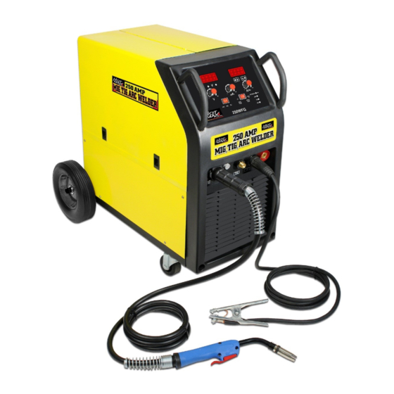
MIG/TIG/ARC Welder
Welder
Operator's Manual
Model 250WFG
Tel: (314) 692-8555
Fax: (314) 692-8578
Web Site: www.hotmaxtorches.com
Advertisement
Table of Contents

Related Manuals for Hot Max 250WFG


Summary of Contents for Hot Max 250WFG
- Page 1 Operator’s Manual Model 250WFG MIG/TIG/ARC Welder MIG/TIG/ARC Welder WARNING: Do not assemble, install, or operate this equipment without reading ALL of this manual and the safety precautions and warnings illustrated in this manual. KDAR Company Tel: (314) 692-8555 1 Mulch Lane Fax: (314) 692-8578 St.
-
Page 2: Electric Shock Can Kill
SAFETY PRECAUTIONS AND WARNINGS PLEASE READ BEFORE USING EQUIPMENT Keep children away from this equipment WARNING Protect yourself and others from possible injury Pacemaker wearers should consult with their doctor before operating Read and follow all instructions in this manual before operating ... -
Page 3: Cylinders Can Explode If Damaged
WELDING SPARKS CAN CAUSE INJURY, FIRE, OR EXPLOSION Remove all flammable materials from the welding area Always have a charged fire extinguisher available in the welding area When not welding make sure the welding tip is not grounded, this causes a heat build up and possible fire ... -
Page 4: Noise Can Damage Hearing
NOISE CAN DAMAGE HEARING Prolonged noise exposure from welding equipment can cause damage if levels of noise exceed the OSHA standards Wear approved hearing protectors Warn other workers nearby of the high noise level and hazard CALIFORNIA PROPOSITION 65 WARNINGS ... -
Page 5: Specifications
Specifications Rated Input 50 Amps @ 220 Volts, 60 Hz, Single Phase Rated Output - Arc 30- 230 Amps, 21.2 to 29.2 Volts DC Rated Output - MIG 50 - 250 Amps, 16.5 to 26.5 Volts DC Rated Output - TIG 20 - 230 Amps, 10.8 to 19.2 Volts DC Duty Cycle - Arc 60% at 230 Amps, 100% at 178 Amps... -
Page 6: Safety Considerations
Installation/Setup Safety Considerations Warning Improper Lifting Techniques Can Cause Injury This unit requires two people when being lifted. Always use proper lifting techniques. Package Contents Item Qty Item Qty Item 6mm x 12mm Bolts 6 Front Caster Wheels (attached) 2 Tank Deck 6mm Lock Washers 6 Gas Hose 5'... -
Page 7: Selecting A Location
Selecting A Location The 250WFG welder should be placed where clean cool air can easily flow through the vents in the front of the unit. Dirt and dust can be drawn into the unit resulting in excessive operating temperatures and shutdowns, therefore, dirt and dust around the unit should be kept to a minimum. -
Page 8: Unit Assembly
Installation/Setup Warning Always unplug the welder before connecting or disconnecting accessories. Unit Assembly 1. With something to prevent scratching under the unit, tip the welder forward onto its face. 2. Using the six 6mm x 12mm bolts and 6mm lock wash- ers, attach the tank deck to the welder as shown in fig- ure 5. -
Page 9: Gas Connection
Installation/Setup Figure 8 Figure 9 Figure 10 Gas Connection Warning Cylinder can explode if damaged. Keep cylinder chained upright to a secure support. Keep cylinder away from areas where it could be damaged. Never lift or move the welder with the cylinder attached. ... -
Page 10: Operation
Operation Gas Hook Up (cont.) 7. Reopen the regulator valve until the flow indicator shows Properly 15 L/min (initial flow setting). The setting may need to be Secured adjusted by the operator to compensate for welding condi- Tank tions. 8. Always close the cylinder valve and open the regulator valve when not in use. - Page 11 Set rocker switch to the left setting for MIG weld- ing. Controls—MIG 1. Output Voltage Control (Dial 1, Figure 13)—The Hot Max infinite setting output voltage control knob adjusts to any setting from 13.7 to 28.5 volts. 2. Speed Control (Dial 2, Figure 13)—Controls the Figure 12 wire feed speed.
- Page 12 Operation Loading & Feeding Wire—MIG Note: Always tur n power off when wor king inside the welder enclosure. Note: It is a good idea to take the contact tip off of the gun prior to feeding the wire. 8” or 12” Diameter Spool 1.
-
Page 13: Changing Drive Roll
Operation Changing Drive Roll The drive rollers have two grooves with the size of the groove etched in the corresponding side of the drive roller. The welder is shipped set up for .040 (1.0 mm). 1. Turn power off and unplug the welder. 2. -
Page 14: Electrical Shock Can Kill
Power Supply Compartment air through again. Repeat flexing the cable and blowing air through until no dirt comes out. The Hot Max 250WFG does not have any serviceable parts inside the power supply compartment. Do not Contact Tip & Nozzle attempt to service parts in the power supply compart- ment. -
Page 15: Troubleshooting
Troubleshooting Warning Most components of the 250WFG welder are not serviceable by the operator and should only be ser- viced by a qualified repair technician. Unauthorized repairs to these units may result in danger to the operator and will void the factory warranty. For your safety, please follow all safety precautions found throughout this manual. - Page 16 Troubleshooting Problem Possible Cause Arc is unstable—Poor starting 1. Check to insure proper input voltage to the weld- er. Check the plug to make sure the unit was wired correctly for 230V. 2. Check electrode polarity to make sure it is cor- rect for the process being used.
- Page 17 Additional Accessories/Replacement Parts for 250WFG Model 23242 Model 23241 36V Heated Regulator/Flow Meter 250WFG Spool Gun Model 23246 250WFG Replacement Contact Tips 250WFG Replacement MIG Nozzle Model 23247 - .025” Contact Tip Model 23248 - .030” Contact Tip Model 23249 - .035” Contact Tip Model 23250 - .040”...
- Page 18 Additional Accessories/Replacement Parts for 250WFG Model 23245 250WFG Replacement Electrode Holder Model 23243 250WFG Replacement MIG Gun Model 23258 Model 23244 250WFG Replacement Ground Clamp 250WFG Replacement TIG Gun Model 23240 250WFG Replacement TIG Foot Pedal Model 23201 Replacement Standard Regulator...
-
Page 19: Warranty
90 days from the date of original purchase. The product covered under this warranty is the Exclusions and Limitations: 250WFG. KDAR Company makes no other warranty of KDAR Company, and its affiliates, will repair or any kind, express or implied. Implied warran- replace, at KDAR’s sole discretion, parts found to... - Page 20 KDAR Company 1 Mulch Lane St. Louis, MO 63044 Phone: (314) 692-8555 Fax: (314) 692-8578 Rev. 2 - Nov 2013...
Need help?
Do you have a question about the 250WFG and is the answer not in the manual?
Questions and answers