Table of Contents
Advertisement
Quick Links
Advertisement
Table of Contents

Summary of Contents for IBC BoilerNet Interface Controller II
- Page 1 BoilerNet Interface Controller II...
- Page 2 IBC Web Site: www.ibcboiler.com In the interest of improving the internal design, operational function, or reliability of our products, IBC Technologies reserves the right to alter or change the product described in this manual, and any associated documentation and specifications without notice.
-
Page 3: Table Of Contents
BoilerNet Interface Controller II Table of Contents Introduction ................................ 1 Configuration .............................. 1 IP Setup .............................. 1 BACnet Setup............................2 Configuring Site and Alert Data ......................2 1.3.1 Configuring Site Data ........................4 1.3.2 Configuring the Alert Data ......................6 SD-Card .............................. - Page 4 BoilerNet Interface Controller II 4.16 Run Profile ............................34 BACnet Interface ............................35 Site Requirements ..........................35 BACnet Objects ..........................38 Multi-value Objects ..........................41 Enclosure Installation Notes ........................43 Troubleshooting Notes ..........................44 Bootloader Configuration .......................... 45 Technical Specifications ........................... 48...
-
Page 5: Introduction
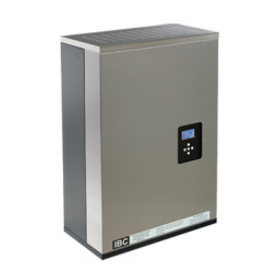
BoilerNet Interface Controller II Introduction The IBC BoilerNet Interface Controller ("BIC") provides both Web and BACnet/IP interfaces to IBC’s line of high efficiency condensing boilers, including the VFC 15-150, VFC 45-225, SL 80-399, and others. It can interface from 1 to 24 IBC boilers using IBC’s BoilerNet communications interface. -
Page 6: Bacnet Setup
Doing so could result in data loss, and/or corruption of the SD-Card. The SD-Card must be writable (not "locked") while in use in the BIC II. All system configuration data is stored in the "ibc" directory on the BIC II’s SD-Card. Figure 1 V1.00.6... - Page 7 BoilerNet Interface Controller II The site information must be entered into the "site.dat" file, and optionally the "alerts.dat" file before the ® BoilerNet Interface Controller can be used. There are many text editors (WordPad , for example) can be ®...
-
Page 8: Configuring Site Data
BoilerNet Interface Controller II 1.3.1 Configuring Site Data When you open the "site.dat" file, it should appear similar to that shown in Figure 2 below. Figure 2 Table 1 - "site.dat" Field Description Field Field Name Field Description Max. Size... - Page 9 BoilerNet Interface Controller II (1) If a dynamic IP address is to be obtained from a DHCP server, then "ipaddr", "ipmask", "ipgate", "ipdns1", and "ipdns2" should all be set to "0.0.0.0" (a dynamic IP address is generally not recommended). (2) "ipdns2" is optional. Set to "0.0.0.0" if not used.
-
Page 10: Configuring The Alert Data
All site information is stored in the "alert.dat" file in the "ibc" directory on the BIC’s SD-Card. When you open the "site.dat" file, it should appear similar to that shown in Figure 4 below. -
Page 11: Sd-Card
The BIC II can support both "standard" and "SDHC" SD-Cards. A 2GB SD-card is more than sufficient for the BIC's operation. IBC will typically supply a SD-Card with the BIC. Please contact IBC if a new or replacement SD-Card is required. The SD-Card is specially formatted with both a Windows compatible partition, and a "hidden"... -
Page 12: Installation
Also try to keep data and power cables separated. 3.2 Power and Enclosures The BoilerNet Interface Controller II requires a power source of 5VDC at 7.5 watts minimum. This is typically supplied from a 120VAC switching power adapter; therefore there should be a 120VAC outlet located reasonably close the where the BIC will be located. -
Page 13: Boilernet Connections
Resistance 25.5 ohms/1000' Full specifications and information can be found on the Cerco web site: http://www.cercocable.com. Please contact IBC if any additional information is required. Figure 5 On the boiler's controller board, the "Boiler Net +" is the "CANH" connection, the other terminal is "Boiler Net –", which is the "CANL"... -
Page 14: Configuring The Boilers
BoilerNet Interface Controller II Figure 6 Please also refer to IBC document "Tech Memo 2310081 – Multiple Boiler Systems" for additional information. Important: The BoilerNet (CAN-bus) interface on both the BIC II and the boiler's controller can be damaged by static electricity and other stray voltages and currents. Proper precautions must be used when installing and handling the communications cable and wiring. -
Page 15: Operation
Note that it takes approximately 2 minutes for the BoilerNet Interface Controller II to initialize before the BACnet or web interfaces will be available. For a first time start-up, or if Network and/or BACnet settings have been changed, the start-up time will be approximately 4 minutes. -
Page 16: Web (Html) Interface
Please refer to user manual for your boiler for a description of all the individual fields and their values. This manual assumes that the user is experienced in the setup and use of IBC boilers, and boiler systems and installations in general. - Page 17 BoilerNet Interface Controller II Figure 7 Only basic information regarding the BoilerNet system will be initially displayed on the opening screen. You must "Login" using a valid user name and password to be able to access and alter detailed information regarding the BIC II and the individual boilers on the network.
- Page 18 BoilerNet Interface Controller II The Web Interface and the boiler's screen and keypad should not be used simultaneously for entering or altering settings. If a key on the boiler's keypad is pressed, then the Web Interface will be "locked out" for a period of 2 minutes from the last key press;...
-
Page 19: User Passwords
BoilerNet Interface Controller II 4.1 User Passwords The Web Interface employs a password system to control access. Up to 10 User Accounts can be configured. Figure 8 Note that both the "User ID" and "Passwords" are case sensitive, both on this screen and when logging in using the Web interface. - Page 20 There are 2 default User ID's that will have been factory configured. User ID "ibc" is the default for all operations, while User ID "BACnet" is for any BACnet operations that require a password. The password for both ID's is set to "boiler"...
-
Page 21: Site Data
BoilerNet Interface Controller II 4.2 Site Data The "Site Data" screen allows all the information in the "site.dat" file to be configured. Note that this screen is not accessible until after an IP address has been initially assigned through editing the "site.dat"... - Page 22 If you are rebooting the IBC, make sure that it is not in use by anyone else before it is rebooted. It will take approximately 3 to 4 minutes for the BIC II to reboot when network or BACnet settings are altered.
-
Page 23: Alert Data
BoilerNet Interface Controller II 4.3 Alert Data The BIC II can be configured to send an E-Mail alert when a problem is detected with a boiler. This screen allows the information in the "alert.dat" file to be configured, which contains the information for the SMTP server to be used for sending the E-Mail through. -
Page 24: Site Log
BoilerNet Interface Controller II 4.4 Site Log This is the event log for the BoilerNet Interface Controller. This displays events for the BIC II itself. For the logs for the individual boilers, please refer to sections "4.14 - Boiler Logs" and "4.15 - Boiler Error Logs". -
Page 25: System Status Display
BoilerNet Interface Controller II 4.5 System Status Display An example of the System Status Display is shown below: Figure 12 Note that in this example there is a after Boiler 01; this indicates that this boiler is the "Master"... - Page 26 BoilerNet Interface Controller II If there is no master boiler in the system, then "Boilers Responding" and "Boilers Firing" are not applicable, and "Target", "Actual", "Outdoor" and "Indoors" temperatures will be displayed from the first online boiler in the list.
-
Page 27: Boiler Status Display
BoilerNet Interface Controller II 4.6 Boiler Status Display This is the main status of an individual boiler on the network. All settings and information regarding the boiler is subsequently accessed from this screen. Figure 13 V1.00.6... -
Page 28: User Settings
BoilerNet Interface Controller II 4.7 User Settings Figure 14 V1.00.6... -
Page 29: Setbacks
BoilerNet Interface Controller II 4.8 Setbacks Figure 15 Note that the boiler's use of the setbacks is controlled on the "4.7 - User Settings" screen. V1.00.6... -
Page 30: Installer Settings
BoilerNet Interface Controller II 4.9 Installer Settings Figure 16 To alter the "Load Type" for a load, select the desired Load Type from the pull-down box, then select "Save". Once the "Load Type" is set to the desired type, you can then edit the settings for the load. - Page 31 BoilerNet Interface Controller II Whenever the "Load Type" is altered, always verify that the settings for the load are indeed correct for your system. As previously mentioned, if the "Load Type" is altered, some of the Load Settings may be reset to the system default values.
-
Page 32: Load Settings
BoilerNet Interface Controller II 4.10 Load Settings An example of the screen for a "Reset Heating" load is shown below. The actual fields displayed will vary by the Load Type selected. If the Load Type is altered through "4.9 - Installer Settings", always verify that the load settings are in fact correct for your system. -
Page 33: Multi-Boiler Settings
BoilerNet Interface Controller II 4.11 Multi-Boiler Settings Figure 18 V1.00.6... -
Page 34: Cleaning Information
BoilerNet Interface Controller II 4.12 Cleaning Information Figure 19 When the boiler has been cleaned, select "Yes" from the "Boiler Cleaned" pull-down, and then click "Save". The "Cleaning Counter" will then be reset, and the "Last Cleaned" date updated. -
Page 35: Diagnostics
BoilerNet Interface Controller II 4.13 Diagnostics This screen is intended for use by, or on the advice of, IBC or other qualified service personnel only. "Supervisor" or higher security rights are required to access this screen. Do not alter any value on this screen unless directed to do so by IBC technical personnel. -
Page 36: Boiler Logs
BoilerNet Interface Controller II 4.14 Boiler Logs Figure 21 Note that in this particular example, the boiler was not configured for a Remote Load; therefore the "Remote On-Time" is zero. V1.00.6... -
Page 37: Boiler Error Logs
Each boiler maintains a log of the last 8 "event" and "watchdog" errors that have occurred on it. The information in the logs is mainly intended for use by IBC service personnel. If you notice errors are frequently occurring, you should contact your installer or IBC service personnel. This may indicate a site problem that needs to be addressed, or a setting in the boiler that needs to be adjusted. -
Page 38: Run Profile
BoilerNet Interface Controller II 4.16 Run Profile This screen provides a graphical summary of the time the boiler used servicing each of the Loads, as well as the modulation (or throttle) percentage being used while servicing each of the individual loads. -
Page 39: Bacnet Interface
BoilerNet Interface Controller II 5 BACnet Interface The BoilerNet Interface Controller provides BACnet "Server" functionality over a BACnet/IP interface. To make use of the BIC II's BACnet capabilities, a properly configured BACnet Operator's Workstation or BACnet Web Server software package is required. The BoilerNet Interface Controller has been tested ®... - Page 40 BoilerNet Interface Controller II An example of a BACnet object list obtained from a BoilerNet Interface Controller is shown below: Figure 24 V1.00.6...
- Page 41 BACnet Operator Workstation software will be specific to your site and your software package. The integration of the BoilerNet Interface Controller and the IBC boilers into a new or existing BACnet installation will be dependent on your particular site and the BACnet software package(s) you are using, and therefore beyond the scope of this document.
-
Page 42: Bacnet Objects
BoilerNet Interface Controller II 5.2 BACnet Objects The BoilerNet Interface Controller will provide a set of BACnet objects for each boiler on the network. There is also set of "Master" objects, which are associated with the boiler designated as the "Master" boiler. - Page 43 BoilerNet Interface Controller II Object Name Value Units Object ID Commandable Notes Boiler 1 Supply Setpoint °C AV1018 Boiler 1 Remote Input AV1019 Boiler 1 Inlet/Outlet Sensor BV1001 Boiler 1 Remote Loop Sensor BV1002 Boiler 1 Cleaning Required BV1003...
- Page 44 BoilerNet Interface Controller II Table 5 – Master Objects Object Name Value Units Object ID Commandable Notes Master Target Temp. °C AI1101 Master Actual Temp. °C AI1102 Master Boilers Responding AV1101 Master Boilers Firing AV1102 Master Outdoor Temp. °C AV1103 ...
-
Page 45: Multi-Value Objects
BoilerNet Interface Controller II 5.3 Multi-value Objects Table 7 – MV1001 – Operating Status Standby Purging Igniting Heating Circulating Error Initialize Service Restart Unknown Table 8 – MV1002 – Error Message None Water High Limit Exceeded Vent High Limit Exceeded Ignition Failure Aux. - Page 46 BoilerNet Interface Controller II Table 10 – MV1004 – Boiler Model Unknown 15-150 45-225 80-399 20-115 Table 11 – MV1005, MV1006, MV1007 – Load Type Reset Heating Set Point External Control Manual Control DHW Loop 2 V1.00.6...
-
Page 47: Enclosure Installation Notes
BoilerNet Interface Controller II 6 Enclosure Installation Notes Please note that it is the responsibility of the installer to adhere to any electrical code requirements which may be applicable to the installation of this equipment. The installation must be performed only by qualified service personnel. -
Page 48: Troubleshooting Notes
BoilerNet Interface Controller II 7 Troubleshooting Notes As mentioned in section "3.3 BoilerNet Connections", BoilerNet uses a CAN-bus interface for communicating between the boilers and the BIC II. The wire type and installation must comply with CAN-bus standards such as ISO 11898 and/or SAE J2284. -
Page 49: Bootloader Configuration
BoilerNet Interface Controller II 8 Bootloader Configuration This is an optional step that will shorten the start-up time of the BIC II controller board in some specific situations. A bootloader comes pre-installed in the controller's Flash memory, which is a customized version of U-Boot. - Page 50 BoilerNet Interface Controller II Texas Instruments X-Loader 1.46 (Nov 29 2010 - 23:10:41) Starting OS Bootloader... U-Boot 2009.11-00005-ge83d2db (Dec 07 2010 - 11:55:34) OMAP34xx/35xx-GP ES1.0, CPU-OPP2 L3-165MHz Craneboard + LPDDR/NAND I2C: ready DRAM: 256 MB NAND: 256 MiB serial Out: serial...
- Page 51 BoilerNet Interface Controller II Enter the following command, followed by the "enter" key: printenv You should see something similar to the following: printenv bootcmd=if mmc init; then if run loadbootscript; then run bootscript; else if run loaduimage; then run mmcboot; else run nandboot;...
-
Page 52: Technical Specifications
IEEE 802.3 Ethernet 10/100 Base-T interface TCP/IP v4 (v6 capable) BACnet/IP via Ethernet interface BoilerNet 2-wire interface via CAN-bus supports up to 24 IBC boilers Features Web Server for IBC BoilerNet BACnet/IP Server for IBC boilers ...
Need help?
Do you have a question about the BoilerNet Interface Controller II and is the answer not in the manual?
Questions and answers